

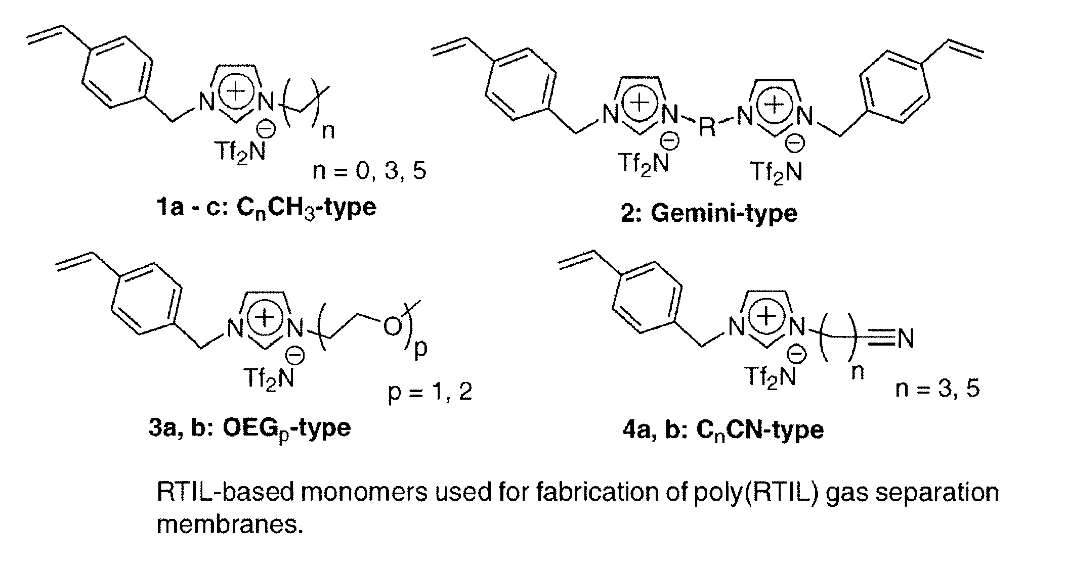
Imidazolium-based room-temperature ionic liquids, polymers, monomers, and membranes incorporating same
a technology of ionic liquids and ionization, applied in the direction of dissolving, chemical/physical processes, greenhouse gas capture, etc., can solve the problems of direct solvent requirements, inability to apply pressure differentials in configurations that have inherently limitations to pressure differentials, and failure of slm configurations, etc., to achieve easy production, high antistatic behavior, and the effect of fine tuning of optical contact clarity and opacity
- Summary
- Abstract
- Description
- Claims
- Application Information
AI Technical Summary
Benefits of technology
Problems solved by technology
Method used
Image

Examples
example 1
Membrane Fabrication
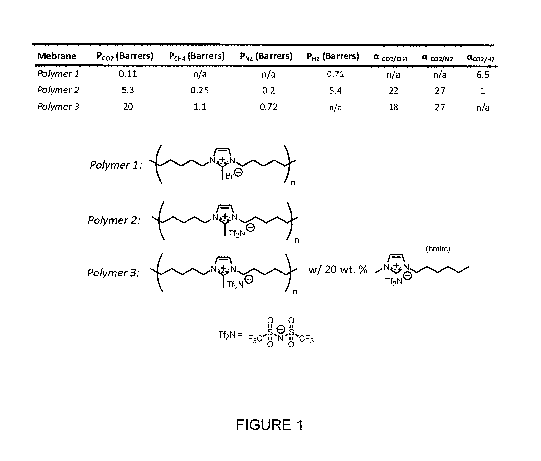
[0159][C2mim][Tf2N] (0.614 g; 1.57 mmol) was added to monomer 1a of FIG. 6 (3.00 g, 6.26 mmol) and the 1:4 (mol:mol) mixture was homogenized to a single liquid phase on a vibrating mixer. Divinylbenzene (0.034 g, 0.33 mmol) was added and the mixing step repeated. Finally, 2-hydroxy-2-methylpropiophenone (0.030 g, 0.18 mmol) was added to the solution and the mixing step repeated a final time. The solution was cast onto a 50×50 cm2 piece of a porous polymer support (Supor200, Pall, AnnArbor, Mich., USA) on top of a quartz plate. A second, identical quartz plate was placed on top and pressure was applied manually to spread the monomer evenly through the support. The excess monomer remained between the quartz plates. The plates were then placed under a 365 nm UV light for 30 min. After this time, the plates were separated with a clean razor blade and the supported polymer film peeled from the surface. The supported area was then punched with a 47 mm diameter stainles...
example 2
Gas Permeability Experiments
[0161]Ideal (single) single gas permeability experiments of the polymers of Example 1 with CO2, N2, and CH4 were carried out at 295K using a time-lag apparatus. Details on the construction, operation, and calculations associated with this equipment can be found as published by our group (Bara et al., Ind. Eng. Chem. Res. 2007; 46: 5397-5404; Bara et al., J. Memb. Sci. 2007; 288:13-19). The membrane was degassed under dynamic vacuum of 2, N2, and CH4 along with the ideal permselectivities of CO2 / N2 and CO2 / CH4 are presented in Table 2.
TABLE 2Ideal gas permeabilities and permselectivitiesin the composite membrane and the neat polymerPermselectivityPoly(RTIL)Permeability (barrers)CO2 / CO2 / membraneCO2N2CH4N2CH4Poly(1a)9.2 ± 050.29 ± 0.010.24 ± 0.013239Poly(1a) +44 ± 3 1.1 ± 0.11.6 ± 0.1392720 mol %[C2mim][Tf2N]
[0162]Assuming solution-diffusion is the mode of transport through poly(RTILs) and poly(RTIL)-RTIL composite membranes, the permeability of a single gas...
example 3
Performance Relative to Other Poly(RTILS) and General Polymer Membranes
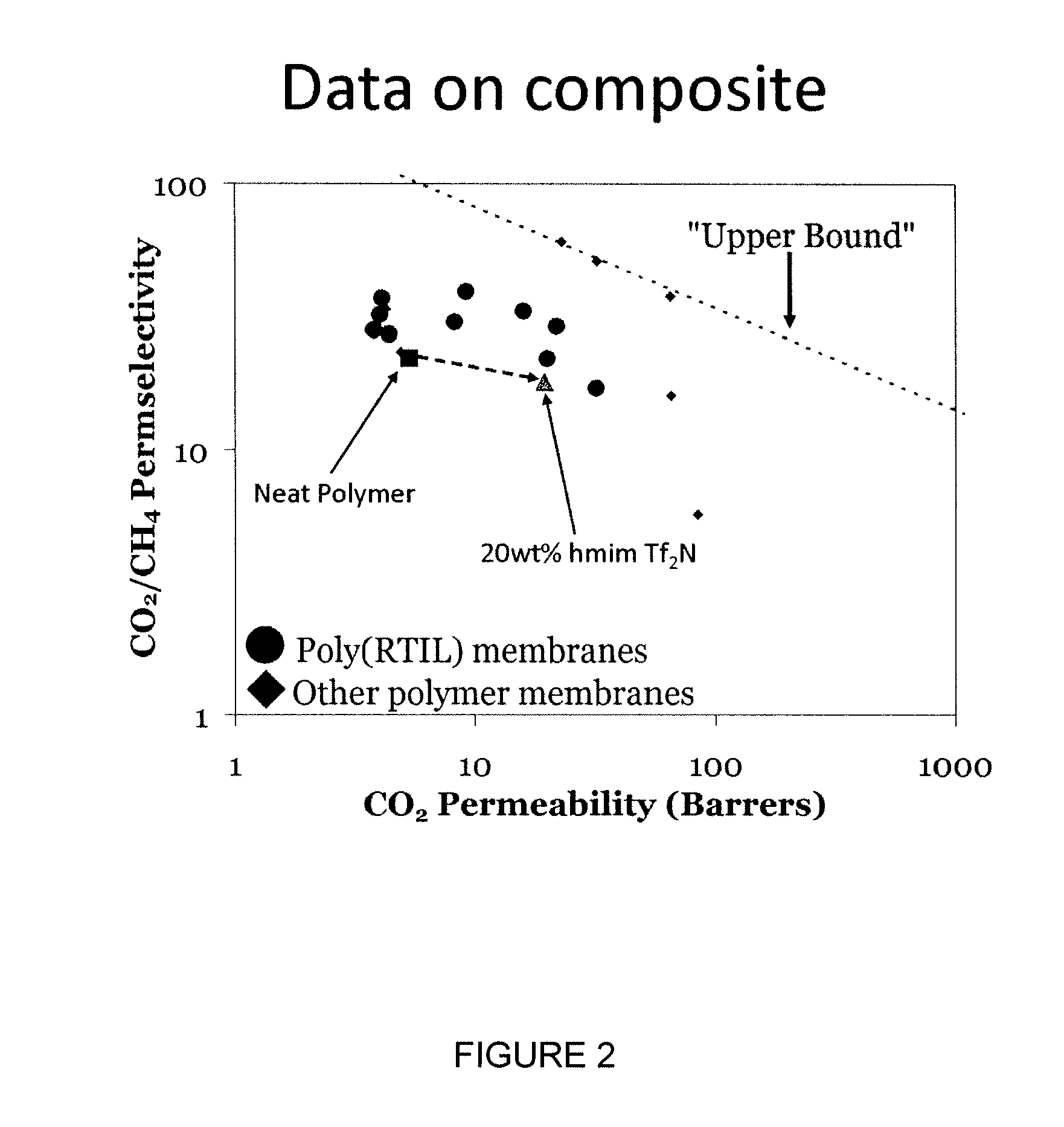
[0168]“Robeson Plots” are widely used for gauging the progress of polymer gas separation membranes (Robeson L M, J. Memb. Sci. 1991; 62:165-185). These log-log charts plot ideal permselectivity for a gas pair against the ideal permeability of the more permeable gas. The “upper bound” can be viewed as a target for researchers to exceed in the development of new membranes. The further to the upper right a material lies is one indicator of its potential for industrial implementation (Baker, R W, Ind. Eng. Chem. Res. 2002; 41: 1393-1411). The “upper bound” has traditionally been defined by glassy polymers with large diffusion selectivities (Robeson L M, J. Membr. Sci. 1991; 62:165-185; Freeman B D., Macromolecules 1999; 32: 375-380). In recent years, many polymers, especially those composed of polymers with polar linkages, such as poly(ethylene glycol) (PEG) derivatives have exceeded the “upper bound” as they exhibit...
PUM
| Property | Measurement | Unit |
|---|---|---|
| mol % | aaaaa | aaaaa |
| temperature | aaaaa | aaaaa |
| thickness | aaaaa | aaaaa |
Abstract
Description
Claims
Application Information