

Preparation of complex fluoride and complex fluoride phosphor
a technology of complex fluoride and phosphor, which is applied in the field of preparation of complex fluoride and complex fluoride phosphor, can solve the problems of insufficient purity, particle shape, emission properties, and difficulty in the industry to implement the method, and achieve the effects of satisfactory emissive properties, high productivity, and uniform siz
- Summary
- Abstract
- Description
- Claims
- Application Information
AI Technical Summary
Benefits of technology
Problems solved by technology
Method used
Image

Examples
preparation example 1
Preparation of K2MnF6
[0057]Potassium hexafluoromanganate (K2MnF6) was prepared in accordance with the procedure described in New Experimental Chemistry Series #8, “Synthesis of Inorganic Compound III”, Maruzen Co., p1166, 1977.
[0058]A reaction vessel of vinyl chloride resin was divided into two compartments by a central partition of fluororesin ion exchange membrane. Platinum plates were set as anode and cathode in two compartments divided by the ion exchange membrane. A hydrofluoric acid aqueous solution having manganese(II) fluoride dissolved therein was fed to the anode side compartment and a hydrofluoric acid aqueous solution was fed to the cathode side compartment. A power supply was connected to the electrodes to carry out electrolysis at a voltage of 3 V and a current flow of 0.75 A. At the end of electrolysis, a hydrofluoric acid aqueous solution containing potassium fluoride at a saturation level was added in excess to the reaction solution in the anode side compartment. T...
example 1
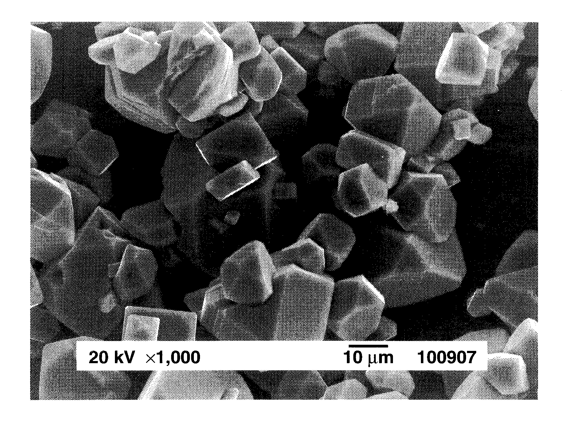
[0059]An aqueous solution of silicon fluoride was prepared by dissolving 4.8 g of silicon dioxide in 100 cm3 of 48 wt % hydrofluoric acid aqueous solution and allowing the solution to cool down to room temperature. The K2MnF6 powder (1.19 g) in Preparation Example 1 was added to the aqueous solution of silicon fluoride and dissolved therein by stirring, obtaining an aqueous solution containing silicon fluoride and K2MnF6 as a first solution. Separately, an aqueous solution of potassium fluoride as a second solution was prepared by dissolving 13.95 g of potassium fluoride in 40 cm3 of 48 wt % hydrofluoric acid aqueous solution and allowing the solution to cool down to room temperature. With stirring, the second solution was slowly added to the first solution over about 3 minutes. Stirring was continued for further about 10 minutes whereupon a pale orange solid precipitated. The solid product was filtered, washed with a small volume of 20 wt % hydrofluoric acid aqueous solution and th...
example 2
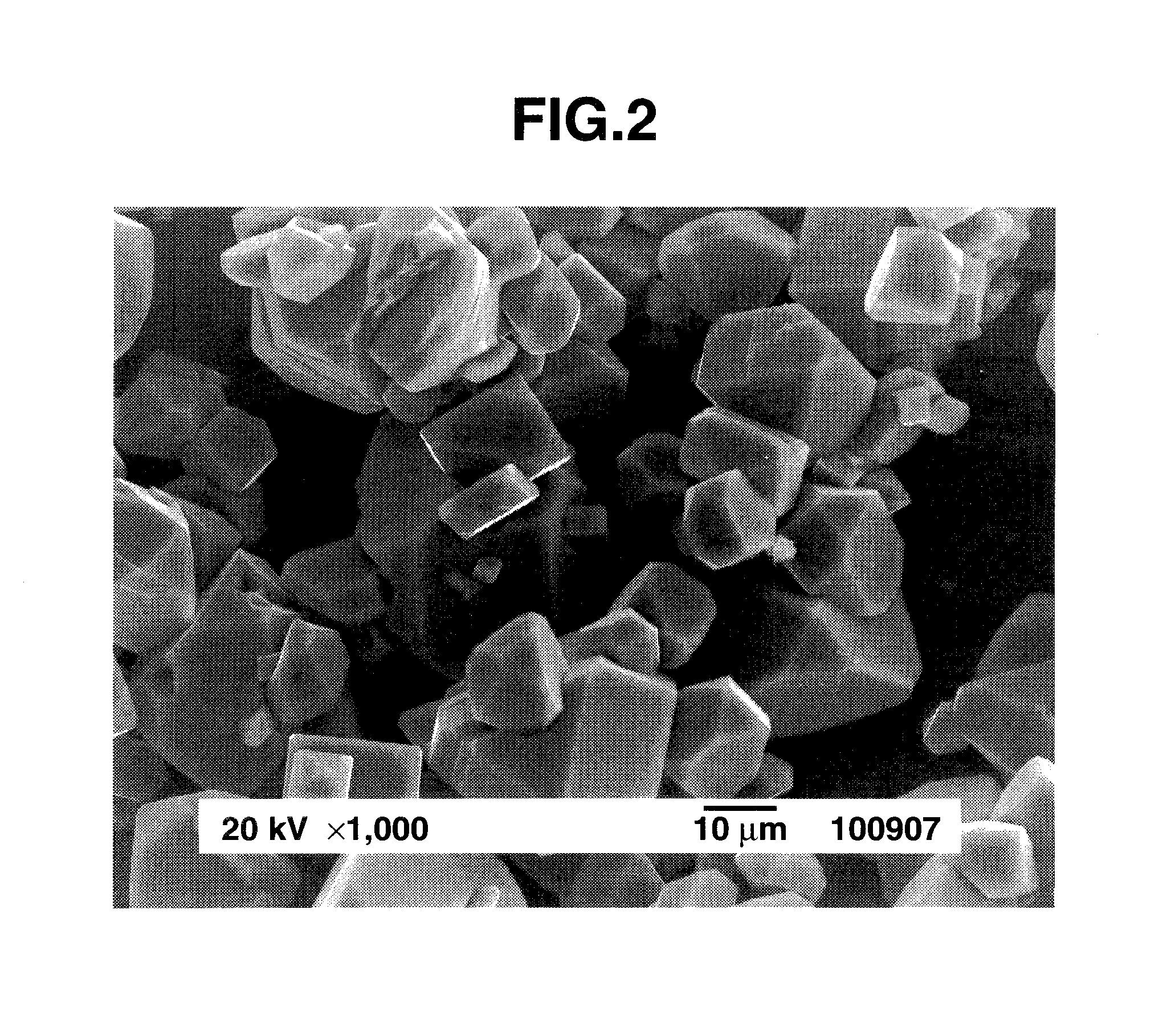
[0063]An aqueous solution of silicon fluoride was prepared by dissolving 4.8 g of silicon dioxide in 100 cm3 of 48 wt % hydrofluoric acid aqueous solution and allowing the solution to cool down to room temperature. The K2MnF6 powder (1.19 g) in Preparation Example 1 was added to the aqueous solution of silicon fluoride and dissolved therein by stirring, obtaining an aqueous solution containing silicon fluoride and K2MnF6 as a first solution. Separately, an aqueous solution of potassium fluoride as a second solution was prepared by dissolving 23.24 g of potassium fluoride in 25 cm3 of water and allowing the solution to cool down to room temperature. With stirring, the second solution was slowly added to the first solution whereupon a pale orange solid precipitated. The solid product was filtered, washed with a small volume of 20 wt % hydrofluoric acid aqueous solution and then ethanol, and dried in vacuum, obtaining 16.79 g of the reaction product.
PUM
| Property | Measurement | Unit |
|---|---|---|
| temperature | aaaaa | aaaaa |
| wavelength range | aaaaa | aaaaa |
| wavelength range | aaaaa | aaaaa |
Abstract
Description
Claims
Application Information