
Semiconductor composition

Active Publication Date: 2012-10-18
SAMSUNG ELECTRONICS CO LTD
View PDF2 Cites 15 Cited by
  • Summary
  • Abstract
  • Description
  • Claims
  • Application Information

AI Technical Summary

Benefits of technology

[0006]The present application discloses, in various embodiments, electronic devices, semiconductor compositions used to make semiconducting layers in the electronic devices, and processes for making such electronic devices. The semiconducting layer is formed from a semiconductor composition that comprises a polymer binder and a crystalline small molecule semiconductor. The small molecule semiconductor has an average crystal size of less than about 50 nanometers. The resulting semiconducting layer achieves high mobility and has excellent stability. The electronic device comprises a semiconducting layer formed from such a semiconductor composition. In specific embodiments, the electronic devices are thin-film transistors.

Problems solved by technology

However, organic or polymeric semiconductors formed by solution processing tend to suffer from limited solubility, air sensitivity, and especially low field-effect mobility.

Method used


Image

  • Semiconductor composition
  • Semiconductor composition
  • Semiconductor composition

Examples


examples

Synthesis of Small Molecule Semiconductor

[0114]2,7-ditridecyl-[1]benzothieno[3,2-b]benzothiophene (2,7-ditridecyl-BTBT) (Formula (49)) was produced as follows.

[0115]A 50 mL Schlenk flask was charged with 2,7-diiodo-BTBT (0.51 grams, 1.036 mmol) and tridec-1-yne (0.934 grams, 5.18 mmol). Toluene (15 ml) and diisopropylamine (15 ml) were added and the reaction was degassed with two freeze / pump / thaw cycles. To the frozen reaction mixture was added bis(triphenylphosphine)palladium(II) chloride (0.145 grams, 0.207 mmol) and copper(I) iodide (0.079 grams, 0.415 mmol). The reaction was subjected to a final freeze / pump / thaw cycle and stirred under argon. After 18 hours the reaction was filtered and the filtrate was concentrated to dryness using a rotary evaporator. The crude product was purified using a Biotage SP1 chromatography system (50 grams SNAP, 0-20% CH2Cl2 in hexanes). The product, 2,7-ditridecyn-1-yl-BTBT, was isolated and recrystallized from hexanes. The structure was confirmed b...

examples 1-3

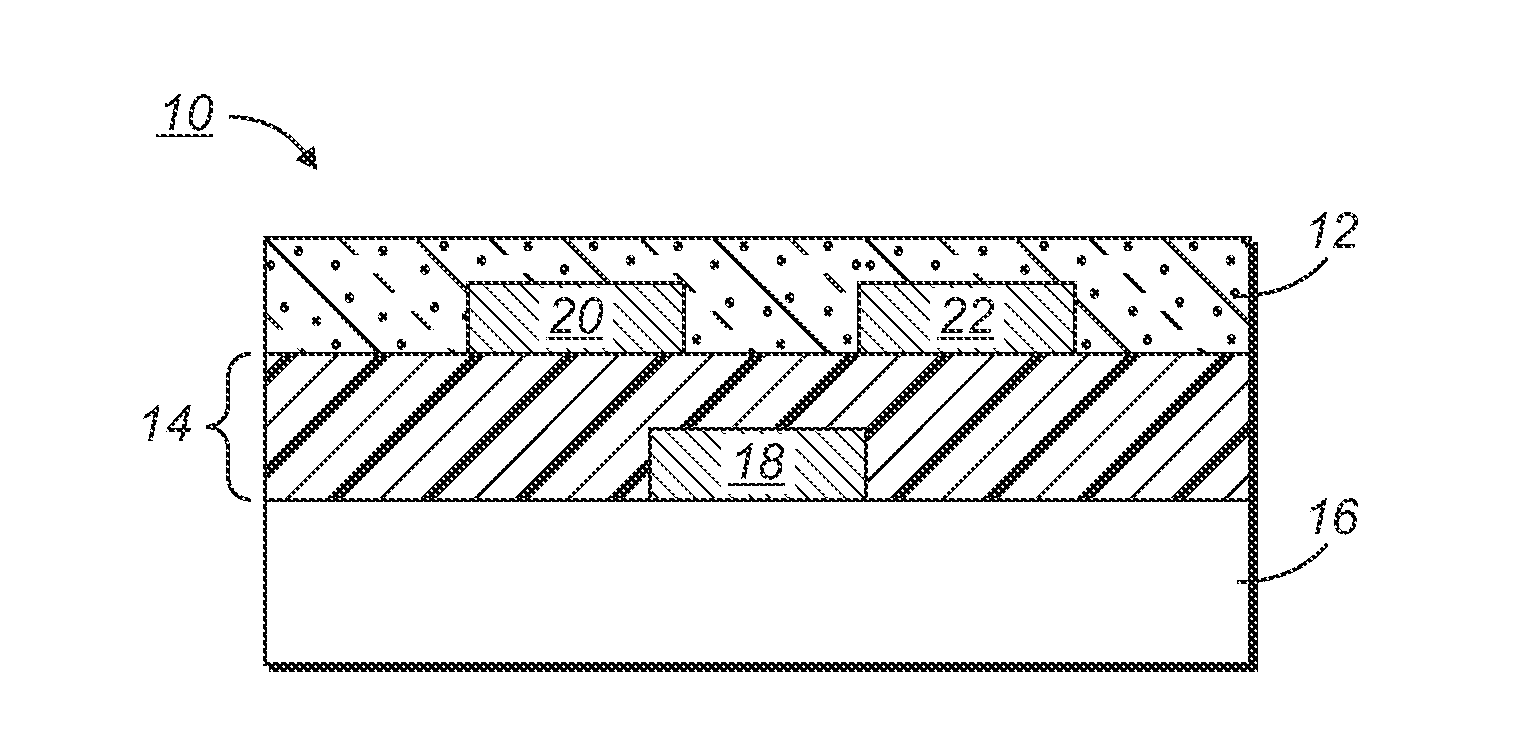
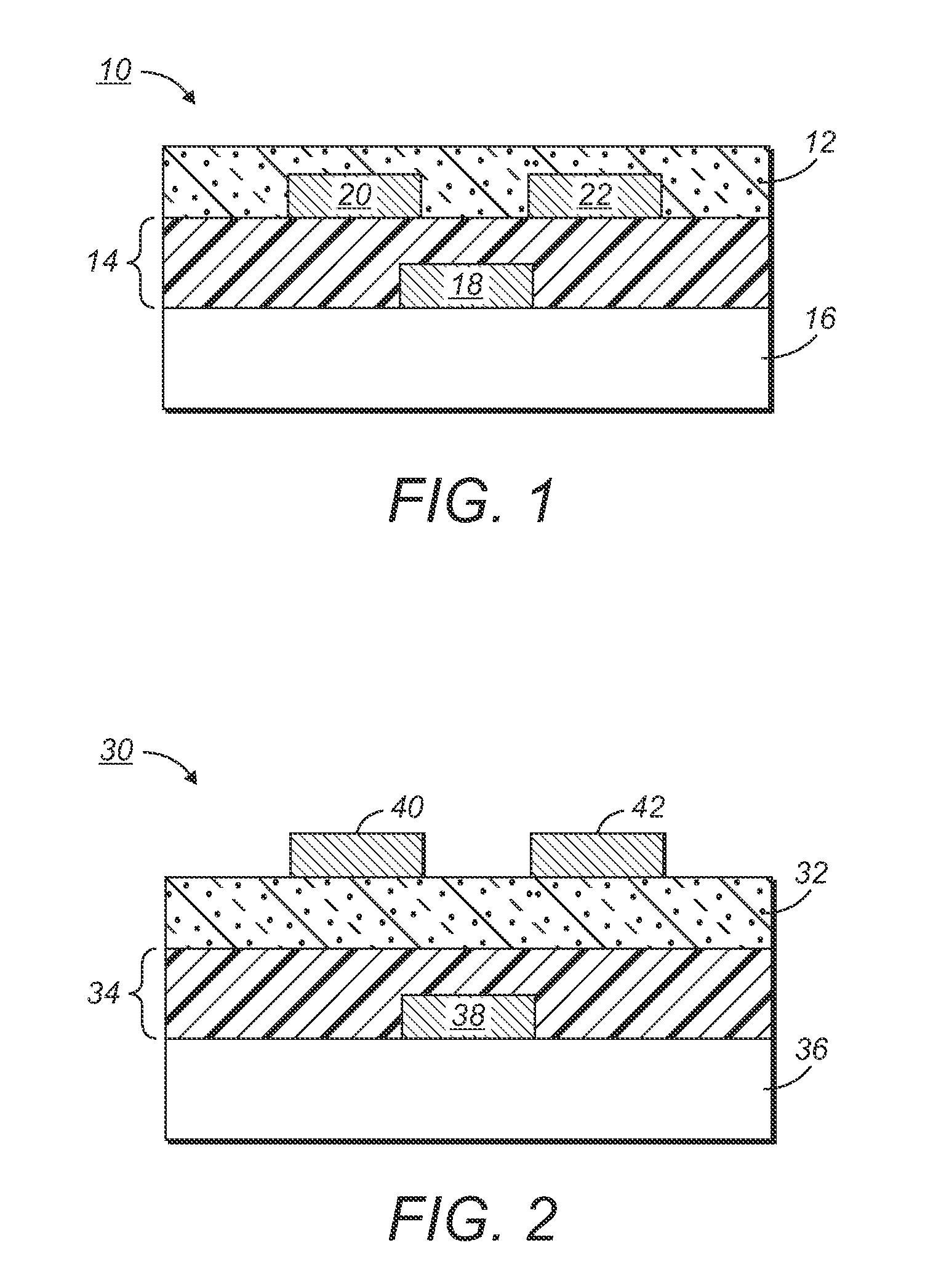
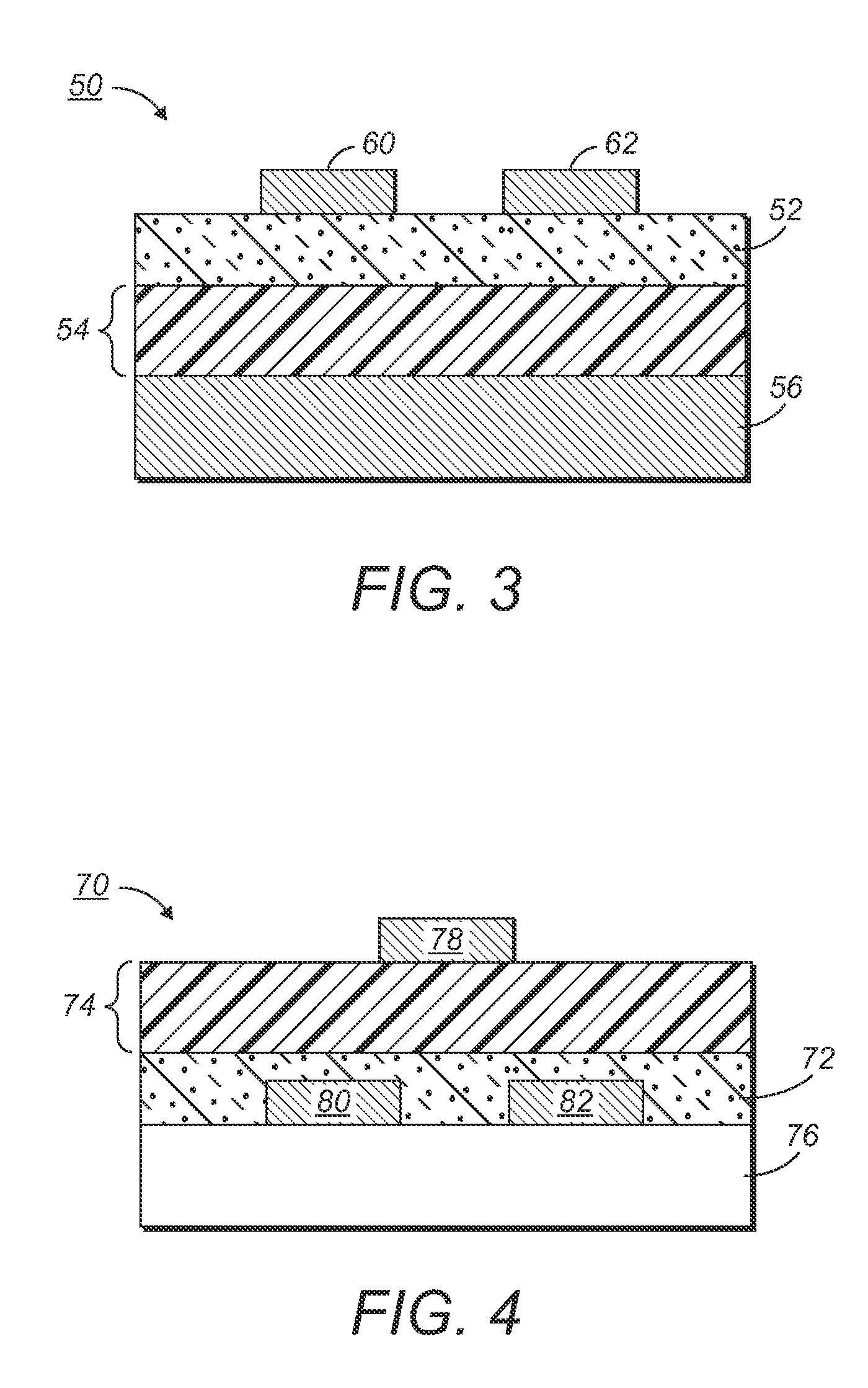
[0120]Devices comprising a semiconducting layer formed from a semiconductor composition comprising 2,7-ditridecyl-BTBT and polystyrene having a weight average molecular weight of about 280,000 were fabricated. An n-doped silicon wafer was used as the substrate. A 200 nm thick silicon oxide dielectric layer was thermally grown as a layer on the substrate. 2,7-ditridecyl-BTBT and polystyrene at a 1:1 weight ratio were dissolved in chlorobenzene in a total amount of 0.7 wt % of the resulting solution. The solution was filtered with a 1.0 μm syringe and spin coated onto the substrate at different spin speeds.

[0121]In Example 1, the solution was spin coated onto the substrate at a spin speed of 1,000 rpm.

[0122]In Example 2, the solution was spin coated onto the substrate at a spin speed of 2,000 rpm.

[0123]In Example 3, the solution was spin coated onto the substrate at a spin speed of 4,000 rpm.

[0124]Multiple devices were made under the conditions of each Example. After drying at 70 to 8...

examples 4-8

[0127]Several batches of devices were fabricated and X-ray diffraction studies were conducted to obtain more quantitative results. In each case, the semiconducting layer was spin coated at a speed of 4000 rpm.

[0128]In Examples 4-6, the small molecule semiconductor was 2,7-ditridecyl-BTBT and the semiconducting layer was not annealed.

[0129]In Example 7, the small molecule semiconductor was 2,7-ditridecyl-BTBT and the semiconducting layer was annealed at 130 degrees C. for 10 minutes.

[0130]In Example 8, the small molecule semiconductor was BTBT and the semiconducting layer was not annealed.

[0131]Table 2 summarizes the performance of transistors of Examples 4-8:

TABLE 2Mobility of Examples 4-8AverageHighestMobilityMobilityExampleSemiconductorAnnealed?(cm2 / V − s)(cm2 / V − s)42,7-ditridecyl-BTBTNo0.50.7752,7-ditridecyl-BTBTNo0.480.8762,7-ditridecyl-BTBTNo0.4400.7272,7-ditridecyl-BTBTYes0.0030.028BTBTNoNo Mobility—

[0132]The X-ray diffraction patterns of Examples 4-8 are shown in FIG. 6. The...


PUM


Abstract

An electronic device, such as a thin-film transistor, includes a semiconducting layer formed from a semiconductor composition. The semiconductor composition comprises a polymer binder and a small molecule semiconductor. The small molecule semiconductor in the semiconducting layer has a crystallite size of less than 100 nanometers. Devices formed from the composition exhibit high mobility and excellent stability.

Description

BACKGROUND[0001]The present disclosure relates to thin-film transistors (TFTs) and / or other electronic devices comprising a semiconducting layer. The semiconducting layer is formed from a semiconductor composition as described herein. When the composition is used in the semiconducting layer of a device, high mobility and excellent stability may be achieved.[0002]TFTs are generally composed of, on a substrate, an electrically conductive gate electrode, source and drain electrodes, an electrically insulating gate dielectric layer which separate the gate electrode from the source and drain electrodes, and a semiconducting layer which is in contact with the gate dielectric layer and bridges the source and drain electrodes. Their performance can be determined by the field effect mobility and the current on / off ratio of the overall transistor. High mobility and high on / off ratio are desired.[0003]Organic thin-film transistors (OTFTs) can be used in applications such as radio frequency ide...

Claims


Application Information

Patent Timeline
IPC IPC(8): H01L51/30
CPCH01L51/0074C07D495/04H01L51/0558H01B1/12H10K85/6576H10K10/484H10K10/462
Inventor WU, YILIANGGARDNER, SANDRA J.WIGGLESWORTH, ANTHONY JAMESLIU, PINGHU, NAN-XING
Owner SAMSUNG ELECTRONICS CO LTD
Learn More