

Porous silicon
a porous silicon and silicon technology, applied in the field of porous silicon, can solve the problems of low yield, poor reproducibility of stain etching, and large internal surface area, and achieve the effects of high solubility, high surface area, and high pore volum
- Summary
- Abstract
- Description
- Claims
- Application Information
AI Technical Summary
Benefits of technology
Problems solved by technology
Method used
Image

Examples
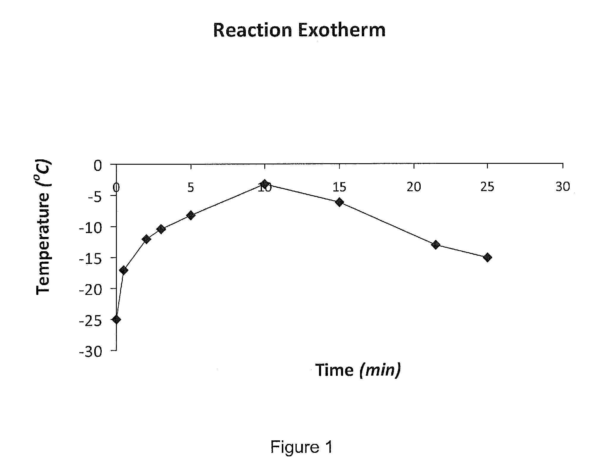
example 1
[0062]600 ml of 1.85M (aqueous) ferric chloride solution was added to 120 ml of 40% (aqueous) hydrofluoric acid. The resulting solution was chilled to −25° C. and poured into a 2L polyethylene bottle containing 10 g of metallurgical-grade silicon powder (d10=0.71 μm, d50=2.10 μm, d90=8.9 μm). The bottle was returned to the chilling bath (−25° C.), covered and stirred with an acid-resistant screw-propeller stirring rod (˜400 rpm). The temperature was monitored in accordance with FIG. 1. At t=˜30 min, 500 ml of de-ionised water (room temperature) was added to the mixture and the diluted mixture immediately poured into a large-area PTFE vacuum-filtration vessel containing a 10 μm MITEX filter membrane. The mixture was filtered until a damp powder remained on the membrane (the filter time was 19 min). The membrane / powder was removed and dried on a hotplate at 45° C. for 24 hr, in air and the resulting powder was weighed. This gave a 23.7% yield of porous silicon which possessed: a surfa...
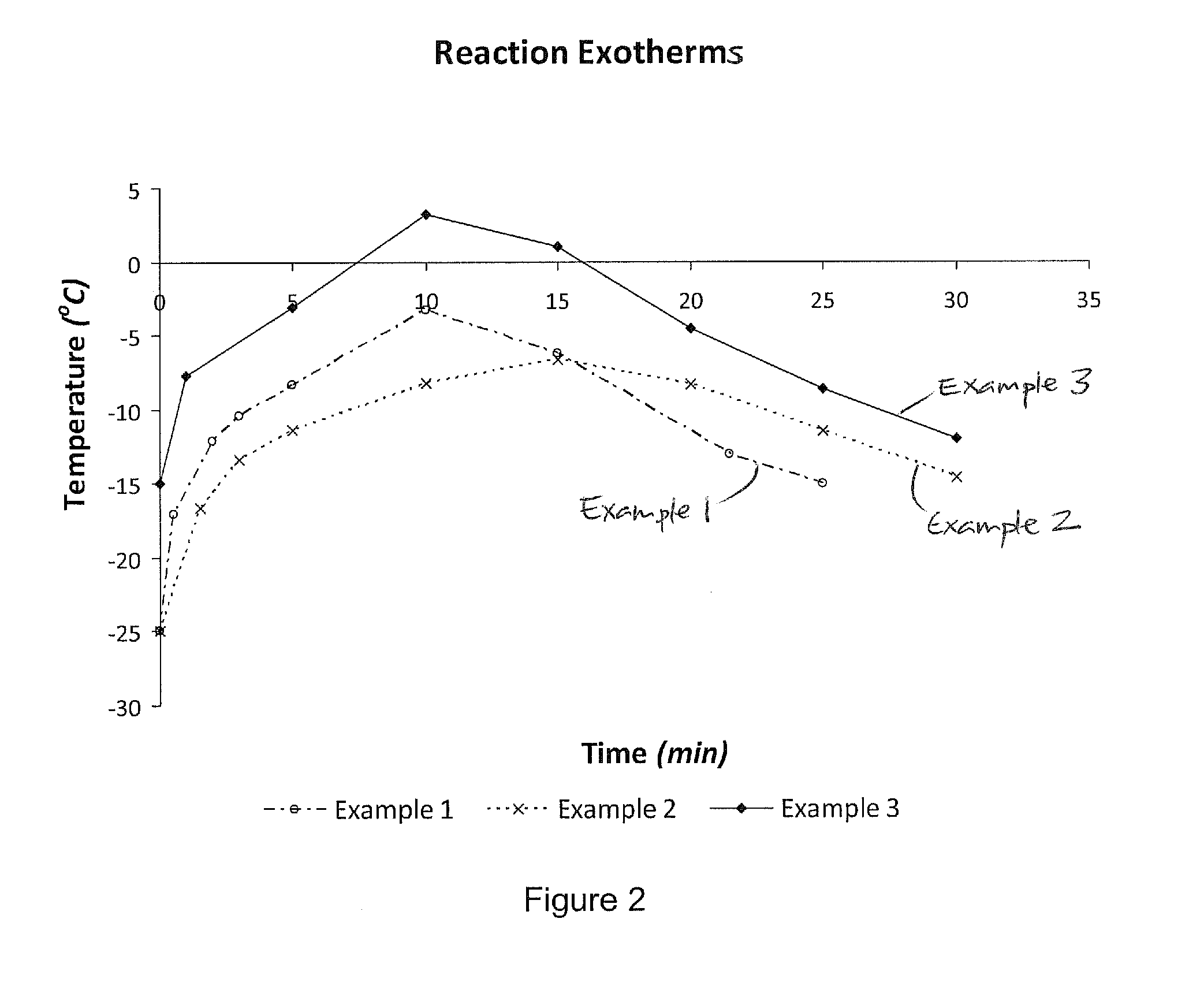
example 2
[0063]600 ml of 1.85M (aqueous) ferric chloride solution was added to 120 ml of 40% (aqueous) hydrofluoric acid. The resulting solution was chilled to −25° C. and poured into a 2L polyethylene bottle containing 10 g of metallurgical-grade silicon powder (d10=0.71 μm, d50=2.10 μm, d90=8.9 μm). The bottle was returned to the chilling bath (−25° C.), covered and stirred with an acid-resistant screw-propeller stirring rod (˜400 rpm). The temperature was monitored in accordance with FIG. 2. At t=˜30 min, 500 ml of de-ionised water (room temperature) was added to the mixture and the diluted mixture immediately poured into a large-area PTFE vacuum-filtration vessel containing a 10 μm MITEX filter membrane. The mixture was filtered until a damp powder remained on the membrane (the filter time was 15 min). The membrane / powder was removed and dried on a hotplate at 45° C. for 24 hr, in air and the resulting powder was weighed. This gave a 40.3% yield of porous silicon which possessed: a surfa...
example 3
[0064]600 ml of 1.85M (aqueous) ferric chloride solution was added to 120 ml of 40% (aqueous) hydrofluoric acid. The resulting solution was chilled to −15° C. and poured into a 2L polyethylene bottle containing 10 g of metallurgical-grade silicon powder (d10=0.71 μm, d50=2.10 μm, d90=8.9 μm). The bottle was returned to the chilling bath (−15° C.), covered and stirred with an acid-resistant screw-propeller stirring rod (˜400 rpm). The temperature was monitored in accordance with FIG. 2. At t=˜30 min, 500 ml of de-ionised water (room temperature) was added to the mixture and the diluted mixture immediately poured into a large-area PTFE vacuum-filtration vessel containing a 10 μm MITEX filter membrane. The mixture was filtered until a damp powder remained on the membrane (the filter time was 14 min). The membrane / powder was removed and dried on a hotplate at 45° C. for 24 hr, in air and the resulting powder was weighed. This gave an 18.7% yield of porous silicon which possessed: a surf...
PUM
| Property | Measurement | Unit |
|---|---|---|
| temperature | aaaaa | aaaaa |
| current density | aaaaa | aaaaa |
| width | aaaaa | aaaaa |
Abstract
Description
Claims
Application Information