
Plastic polarized lens, method for producing the same, and polarized film

a technology of polarized polyvinyl alcohol and lens material, which is applied in the direction of polarizing elements, instruments, applications, etc., can solve the problems of deterioration, polarized film is liable to be peeled off from the lens material during a periphery polishing process, and polarized lens preparation using polarized polyvinyl alcohol film, etc., to achieve high contrast. the effect of property

Active Publication Date: 2013-06-20
HOPNIC LAB
View PDF3 Cites 21 Cited by
  • Summary
  • Abstract
  • Description
  • Claims
  • Application Information

AI Technical Summary

Benefits of technology

The present invention is a plastic polarized lens and a method of producing it that solves various problems in the related art, such as low contrast, poor appearance, and water damage. The plastic polarized lens has improved contrast, reduced visual fatigue, and excellent water resistance. It also has excellent processing characteristics and can be thinner and mass-produced. The polarized film produced by the invention has a polarizing function and a high contrast property, making it suitable for use in polarized lenses.

Problems solved by technology

The polarized lens with a polarized film laid on the surface of the plastic lens material (for example, Japanese Patent Laid-Open Application No. 09-258009 (Patent Document 1)) can make the thickness of the lens smaller, but has a serious disadvantage that the polarized film is liable to be peeled off from the lens material during a periphery polishing process (a process of polishing the edges of the lens to match a predetermined shape).
However, a polarized lens prepared using a polarized polyvinyl alcohol film has a disadvantage of gradual invasion of moisture from the edge of the lens, or due to the environment from the peripheral portion of the lens toward the central portion and thus, deterioration develops over time.
However, this polarized lens has a disadvantage that the polarized film contained in the lens is clearly visible from outside, which gives an uncomfortable feeling to a person who wears the eyeglasses containing this lens.
In addition, since a composition formed by mixing a diamine and an isocyanate prepolymer has a high viscosity as well as a short pot life, injection of the composition into a lens casting mold having a fixed polarized film therein is troublesome, and the production of a thin lens has been extremely difficult.
Thus, according to the type of the monomers, particularly, there may be cases where the functions of the organic coloring compound are damaged due to the interaction with the monomers or the reactions during a polymerization reaction.

Method used


Image

  • Plastic polarized lens, method for producing the same, and polarized film
  • Plastic polarized lens, method for producing the same, and polarized film
  • Plastic polarized lens, method for producing the same, and polarized film

Examples


example 1

[0304]0.0150 parts by weight of organic coloring compound A, and suitable blending amounts of the dichroic dyes A to H were prepared to give a desired color tone, and mixed with 100 parts by weight of a polyethylene terephthalate resin. The resin made molten using a T die film molding machine was cast by T die and molded into a film, and the film was subjected to a 4-times stretching operation to obtain a polarized film having a thickness of 140 μm. The polarized film contained 134 ppm of the organic coloring compound A.

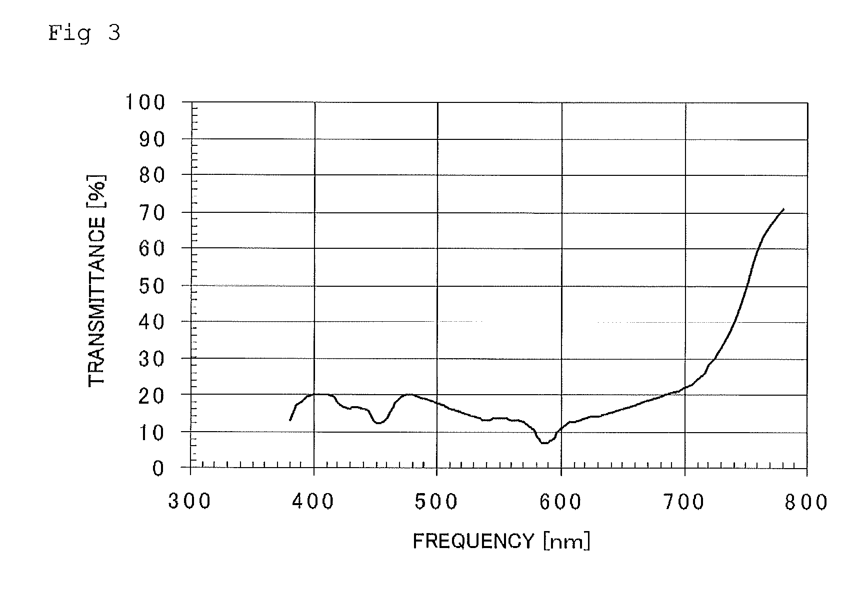
[0305]The absorbance of the obtained polarized film was measured using an absorbance measurement device, UV / VIS SPECTROMETER V-550, manufactured by JASCO Inc. The measurement results are shown in FIG. 3. As shown in FIG. 3, there was a peak of maximum absorption at 588 nm. In addition, the polarized film had polarization characteristics.

[0306]The glass transition temperature of the polyethylene terephthalate-made polarized film as obtained above, which was provided w...

example 2

[0308]The polyethylene terephthalate-made polarized film obtained above in Example 1 [glass transition temperature: 70.7° C.] (thickness 140 μm) was shaped in a curved shape of 2C (curve) at a shaping temperature of 120° C. by a heat pressing method. The polarized film was prepared by cutting the polarized film to match the mold size. This was inserted and installed inside the polarized lens casting mold (glass mold set −5D with a front surface of 2C and a rear surface of 6C) shown in FIG. 2.

[0309]On other hand, 50.6 parts by weight of m-xylylene diisocyanate, 49.4 parts by weight of a mixture of 4,8-dimercaptomethyl-1,11-dimercapto-3,6,9-trithiaundecane, 4,7-dimercaptomethyl-1,11-dimercapto-3,6,9-trithiaundecane and 5,7-dimercaptomethyl-1,11-dimercapto-3,6,9-trithiaundecane, 0.01 parts by weight of dibutyl tin dichloride as a curing promoting agent, 0.1 parts by weight of Zelec UN (registered trademark, manufactured by Stepan Company) as a mold releasing agent and 0.05 parts by wei...

example 3

[0325]The polyethylene terephthalate-made polarized film obtained above in Example 1 [glass transition temperature: 70.7° C.] (thickness 140 μm) was subjected to a heating treatment in an oven at 140° C. for 15 minutes in advance, and then shaped in a curved shape of 6C (curve) at a shaping temperature of 160° C. by a heat pressing method. The polarized film was cut to match the mold size, and then the surface and the back surface of the polarized film were irradiated with plasma for 20 seconds, respectively, using a surface modification device by irradiation with plasma (PS-601 SW type: manufactured by Wedge Co., Ltd.), washed with methanol, and then air-dried. This was inserted and installed inside the polarized lens casting mold (glass mold set with a front surface of 6C and a rear surface of 6C, center thickness: 12 mm). Further, in the same manner as in Example 2, the monomer mixture for injection was injected, warmed from 25° C. to 100° C. in an oven over 16 hours, and then ke...


PUM

PropertyMeasurementUnit
Temperatureaaaaaaaaaa
Fractionaaaaaaaaaa
Viscosityaaaaaaaaaa

Abstract

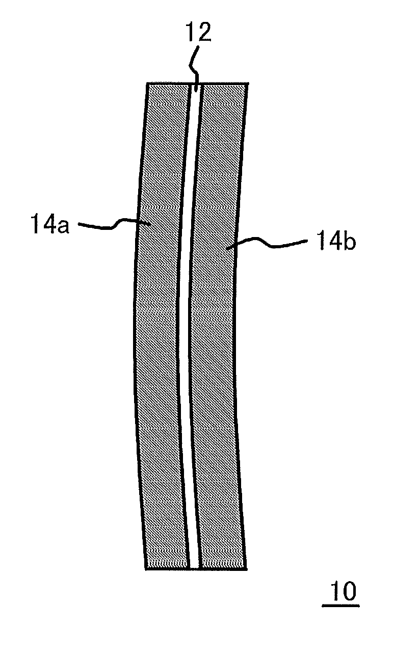
The plastic polarized lens (10) of the present invention contains a polarized film (12) and layers (resin layers) (14a and 14b) comprising a thiourethane-based resin stacked over both surfaces of the polarized film (12), and the polarized film contains an organic coloring compound represented by the following general formula (1).

Description

TECHNICAL FIELD[0001]The present invention relates to a plastic polarized lens, a method for producing the same, and a polarized film.BACKGROUND ART[0002]A polarized lens can prevent transmission of reflected light. Therefore, it is used for, for example, protecting eyes by intercepting strong reflected light outdoors such as on a skiing area or in fishing, and for securing safety during driving a car by intercepting reflected light from a car traveling in the opposite direction.[0003]For a plastic polarized lens, two kinds of polarized lens, that is, a polarized lens with a polarized film laid on the surface of the plastic lens material, and a sandwich structured polarized lens with a polarized film within the plastic lens material, have been proposed. The polarized lens with a polarized film laid on the surface of the plastic lens material (for example, Japanese Patent Laid-Open Application No. 09-258009 (Patent Document 1)) can make the thickness of the lens smaller, but has a se...

Claims


Application Information

Patent Timeline
IPC IPC(8): G02B1/08
CPCB29K2075/00C09B47/00G02B1/041G02B5/3033B29C39/10B29K2995/0034B29C33/10B29C39/12G02B1/08G02B2207/113C08L81/00C08L75/04
Inventor RYU, AKINORIKOBAYASHI, SEIICHIKAMIO, HIROYUKIKOBAYASHI, YOSHIHARUSAKAI, MITSURUAIISO, YOSHIMITSU
Owner HOPNIC LAB
Learn More