Process and plant for treating ore concentrate particles containing valuable metal

a technology of concentrate particles and processing plants, applied in the field of processing, can solve the problems of affecting the efficiency of leaching, forming accretions which could fall down, damage equipment or block gas passage, and high cost of effluent treatment, so as to reduce the risk of corrosion damage by so3, reduce the risk of accretion formation, and reduce the concentration of so3 in the process gas.

Active Publication Date: 2013-11-07
METSO OUTOTEC (FINLAND) OY
View PDF2 Cites 6 Cited by
  • Summary
  • Abstract
  • Description
  • Claims
  • Application Information

AI Technical Summary

Benefits of technology

[0022]A particular object of the invention is to provide a process and plant wherein the risk of corrosion and forming of accretions are reduced during post combustion and down-stream in the gas cleaning system. Further, an object of the invention is to provide a process and plant wherein SO3 concentration in the process

Problems solved by technology

Gold rich calcine are often processed by cyanide leaching but the leaching is only efficient, if the calcine is dead roasted or sulphating roasted.
Known problems in the further processing are:The forming of accretions which could fall down and damage equipment or block gas passage.
The accretions are e.g. formed due to local under cooling of the process gas or on cold surfaces in the equipment.Condensation of arsenic on cold surfaces which will form said accretions.Condensation of acid mist on cold surfaces which will cause corrosion and contribute to formation of accretion.If the acid mist quantity is high, the cost for effluent treatment will also be high.Heat recovery of the system has often been limited to the production of saturated steam which is less favourable for the production of electric energy.
However, in some case

Method used


Image

  • Process and plant for treating ore concentrate particles containing valuable metal
  • Process and plant for treating ore concentrate particles containing valuable metal

Examples


Embodiment Construction

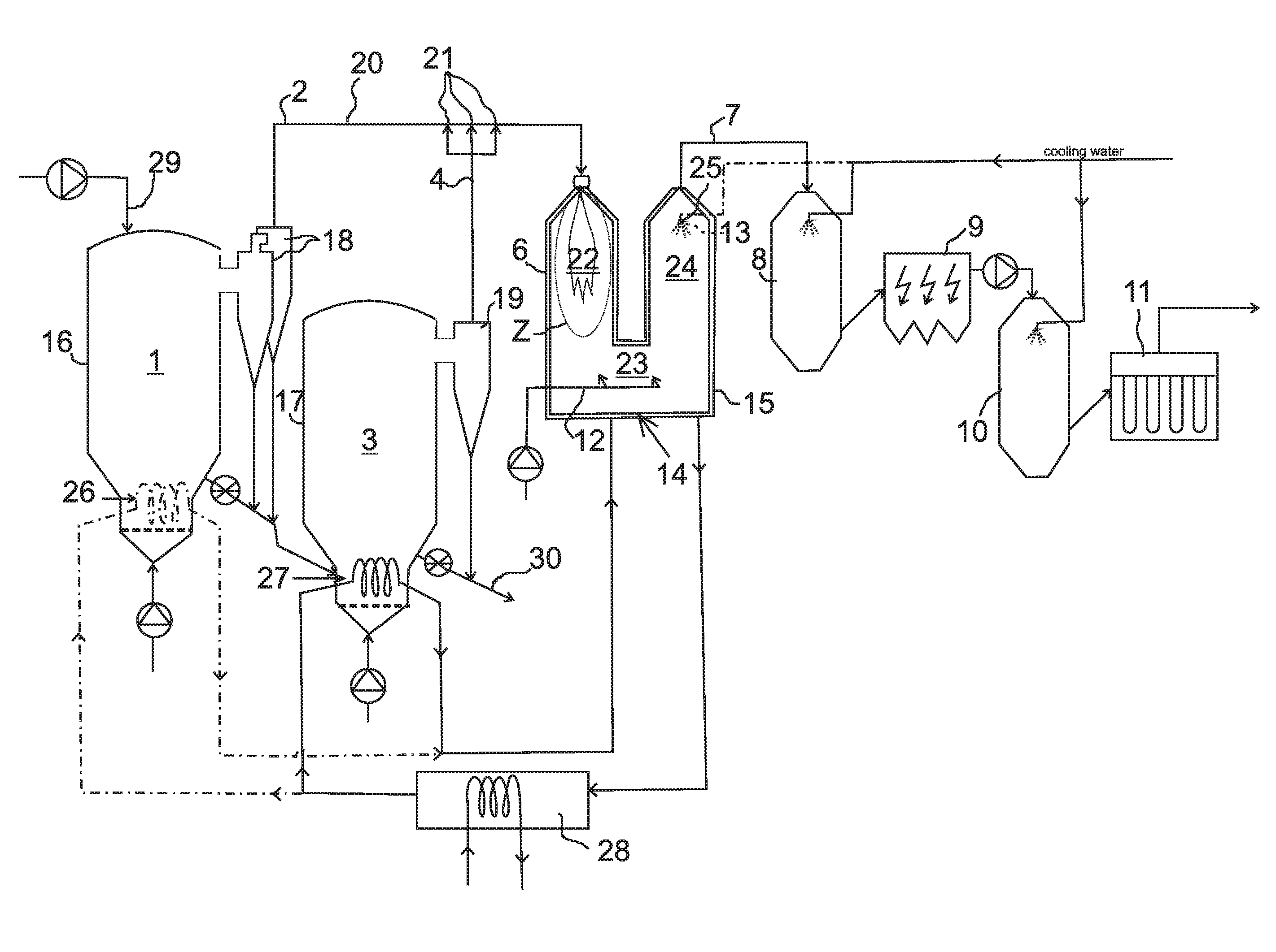
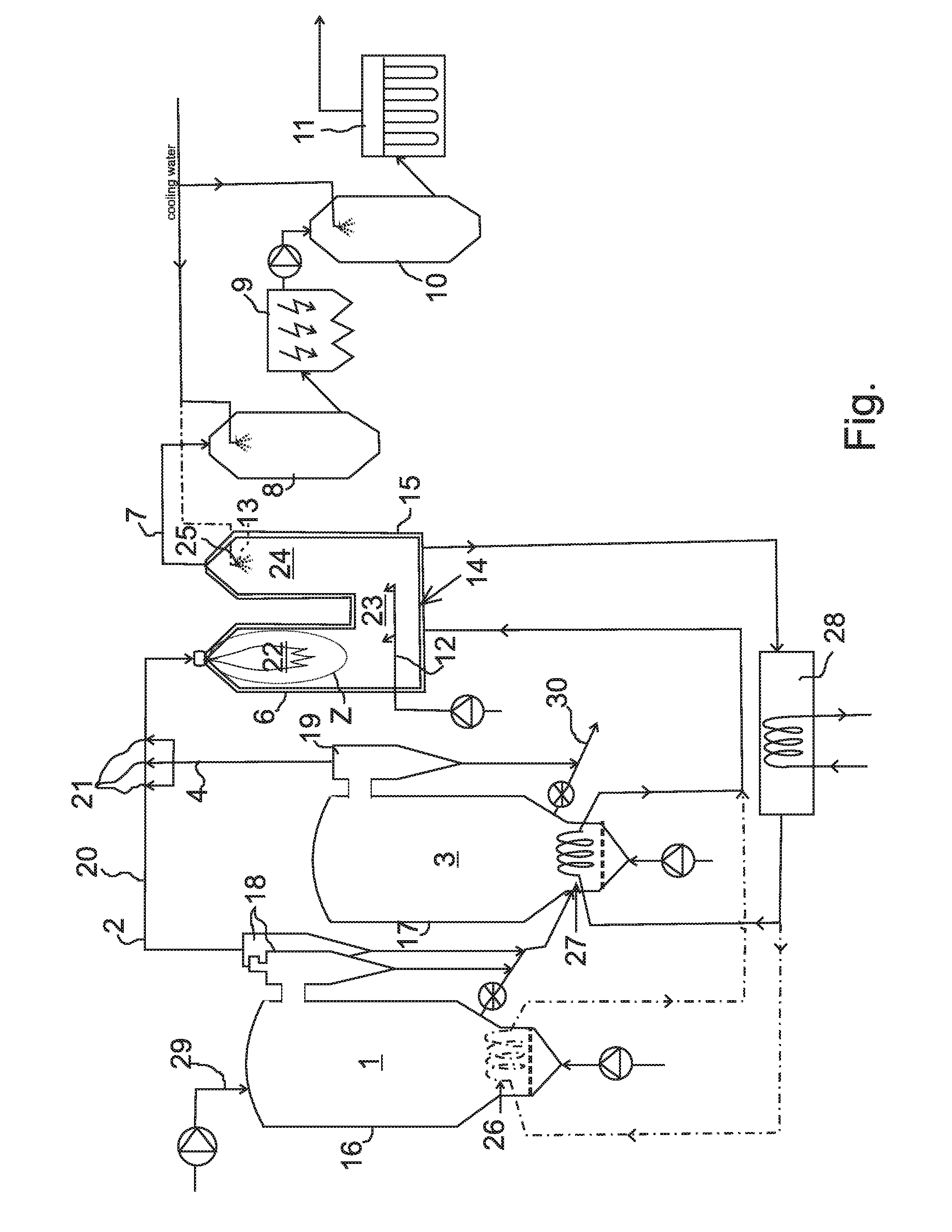
[0056]The flow sheet in FIGURE shows a two stage roasting plant with its off-gas handling system. This process layout is suitable when the raw material is an arsenic contaminated sulfide ore concentrate which valuable particles contain precious metals like gold and silver. Copper and zinc can also be present in large or small quantities. The concentrate is fed at the inlet 29 to the first roasting step 1 which is implemented in a first roasting reactor 16. The first roasting reactor 16 is a first fluidized bed reactor. The first roasting step 1 is a dearsenifying step operating at a very low oxygen potential. A first cyclone separator is arranged to receive process gas with a lot of calcine from the first roasting reactor 16 and to separate from said process gas the calcine and a sulphide rich first process gas component 2 with less calcine. The calcine contains the valuable metals and has a low content of arsenic. The first process gas component 2 leaving the dearsenifying roasting...


PUM

PropertyMeasurementUnit
Temperatureaaaaaaaaaa
Timeaaaaaaaaaa

Abstract

The present invention concerns a process and a plant for treating ore concentrate particles containing valuable metal and having at least arsenic and sulfur containing components. The process comprises a two-stage roasting process comprising a first roasting step (1) made in a first roasting reactor (16) and a second roasting step (3) made in a second roasting reactor (17). A gas mixture is formed from the first process gas component (2) obtained from the first roasting step(1)and from the second process gas component (4) obtained from the second roasting step (3). Post combustion of the gas mixture is made in a post combustion chamber (6). The post combustion operates with said reducing and sulphide rich first process gas component (2) and the second process gas component (4) as oxidizer gas in order to decompose SO3 in the gas mixture to reduce the SO3 content. The risk of accretion formation and corrosion in the post combustion chamber and in subsequent steps is reduced. Finally the exit gas (7) is exposed to sub sequent gas cooling and dust removal steps (8 to 11).

Description

FIELD OF INVENTION[0001]The present invention relates to a process in accordance with claim 1. Further, the present invention relates to a plant in accordance with claim 19. More specifically, the invention relates to the off-gas handling and treatment in said process and plant.BACKGROUND OF INVENTION[0002]Known technique in the art is depicted e.g. in the articles “Roasting developments—especially oxygenated roasting, Developments in Mineral Processing, Volume 15, 2005, Pages 403-432 K. G. Thomas, A. P. Cole”, “Roasting of gold ore in the circulating fluidized-bed technology Developments in Mineral Processing, Volume 15, 2005, Pages 433-453, J. Hammerschmidt, J. Guntner, B. Kerstiens”, and patent documents WO2010 / 003693, U.S. Pat. No. 6,482,373, AU 650783, U.S. Pat. No. 4,919,715.[0003]Copper and gold concentrates containing arsenic are preferably processed by dearsenifying roasting before further treatment by smelting in a copper plant or cyanide leaching.[0004]The dearsenifying r...

Claims


Application Information

Patent Timeline
IPC IPC(8): C22B1/02C22B11/02
CPCC22B1/02C22B1/10C22B11/00C22B15/0013B01D2258/025B01D53/52B01D53/64B01D53/76B01D2251/11C22B11/02C22B5/08C22B5/12F27B15/00F27B15/09F27B15/12
Inventor HOLMSTROM, KELUNDHOLM, KARINBERG, GUNNARGUNTNER, JOCHEN
Owner METSO OUTOTEC (FINLAND) OY
Why Eureka
Try Eureka