Electrochemical separation membrane and the manufacturing method thereof

a technology of electrochemical separation membrane and manufacturing method, which is applied in the direction of filtration separation, separation process, cell components, etc., can solve the problems of low cost of dry type method, poor wet electrolyte transfer effect to separation membrane, and high final price of separation membrane, so as to improve thermal stability and increase the stability of the interface of the electrochemical device

Active Publication Date: 2013-12-12
ENERAGE INC
View PDF2 Cites 21 Cited by
  • Summary
  • Abstract
  • Description
  • Claims
  • Application Information

AI Technical Summary

Benefits of technology

[0017]The technical feature of present invention is to mix and disperse the ceramic precursors and the polymer material uniformly during preparing the polymer solution, such that the ceramic particles are distributed uniformly in the electrochemical separation membrane. Since the existence of the ceramic particles, the ion conductivity, the interface stability of the electrochemical device is increased, and the thermal stability is also improved under the high temperature.

Problems solved by technology

For the lithium ion battery system, since the polarity of the polyolefin polymers is very low, such that the wetting effect of electrolytes to the separation membrane is not good, and the ion electric conductivity of whole lithium ion battery is lower than the ion electric conductivity of the electrolytes.
The cost of the dry type method is low, but the ultimate price of the separation membrane is still high because the conditions of processes are strict to meet the specification of the secondary lithium ion battery.
However, the mixing effect is not noticeably obvious and the particle size of the ceramic particles is hard to control in the processes.
However, the cohesive strength between the composite layer and base material membrane is not good enough, and the stability of separation membrane is also not good.
The technology has problems of low adhesive strength and non-uniform distribution of ceramic particles, and the performance of the separation membrane is affected.
However, those methods make the process difficult and complicated.
As described, most of prior arts add the ceramic particles directly which are coated on two sides of the membrane to form protective layers, and the accuracy of membrane thickness and the distribution of ceramic particles are hard to control.

Method used


Image

  • Electrochemical separation membrane and the manufacturing method thereof
  • Electrochemical separation membrane and the manufacturing method thereof
  • Electrochemical separation membrane and the manufacturing method thereof

Examples


experimental example 1

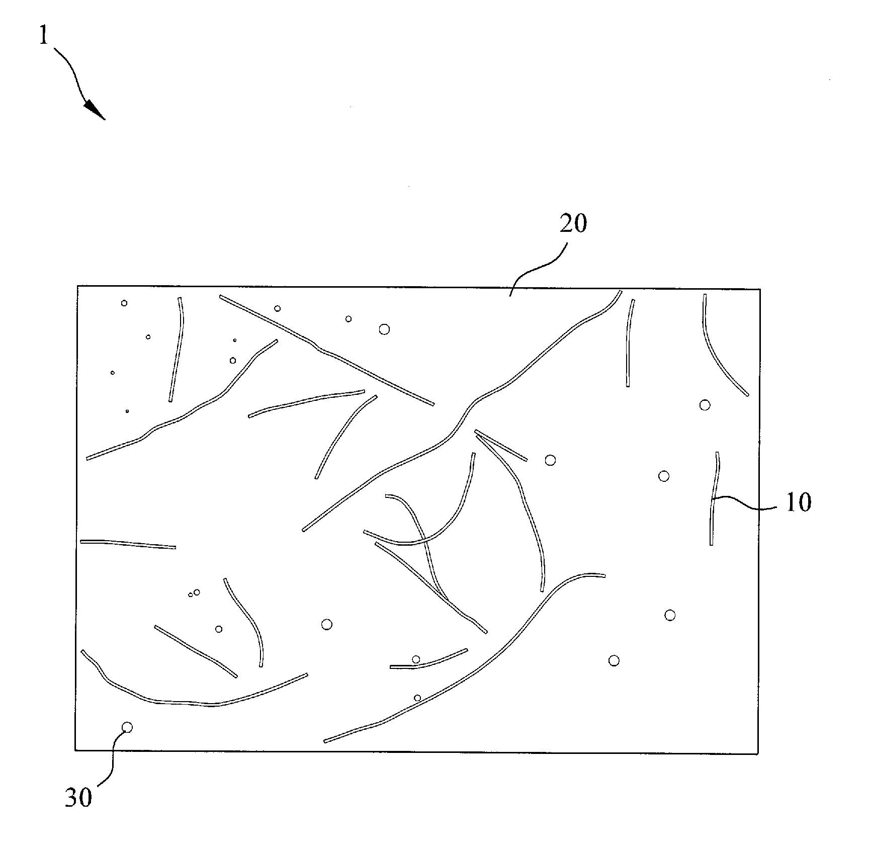
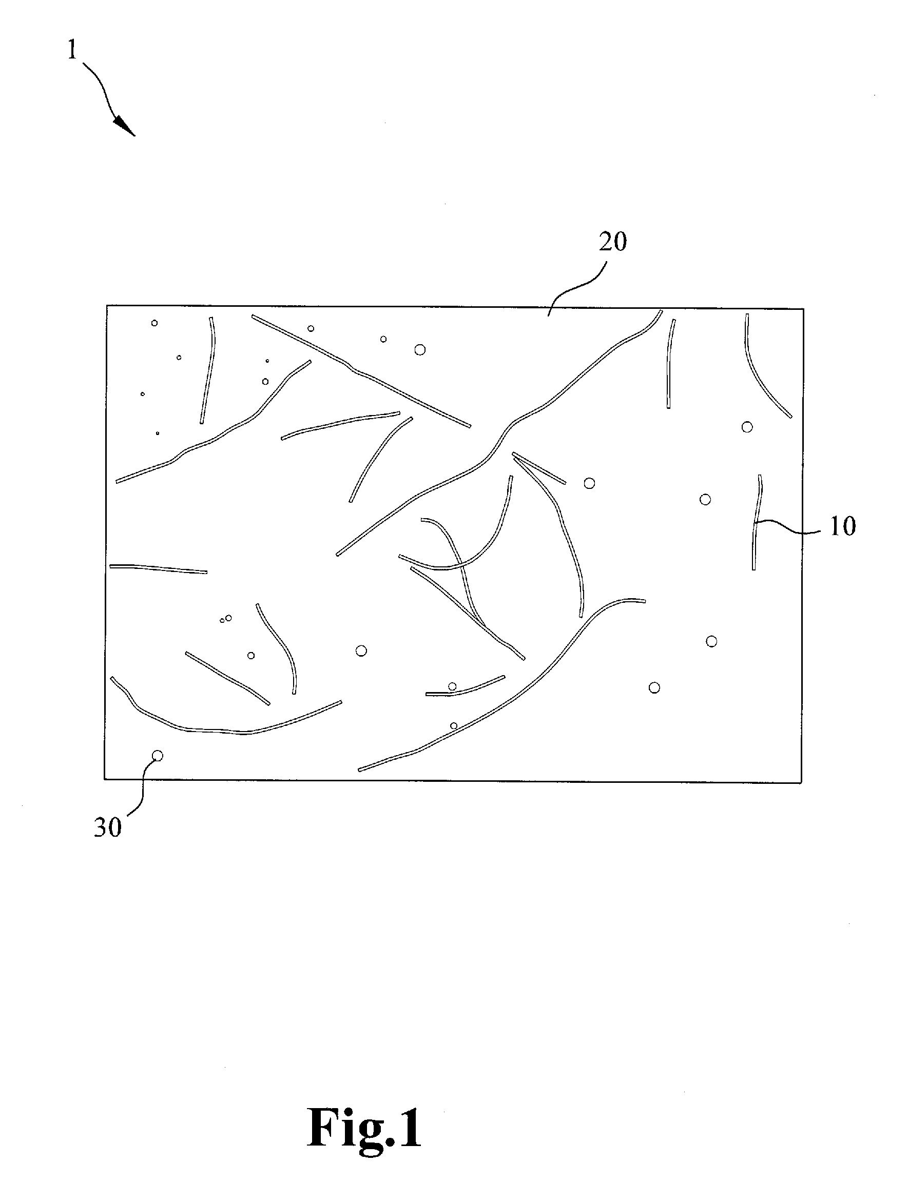
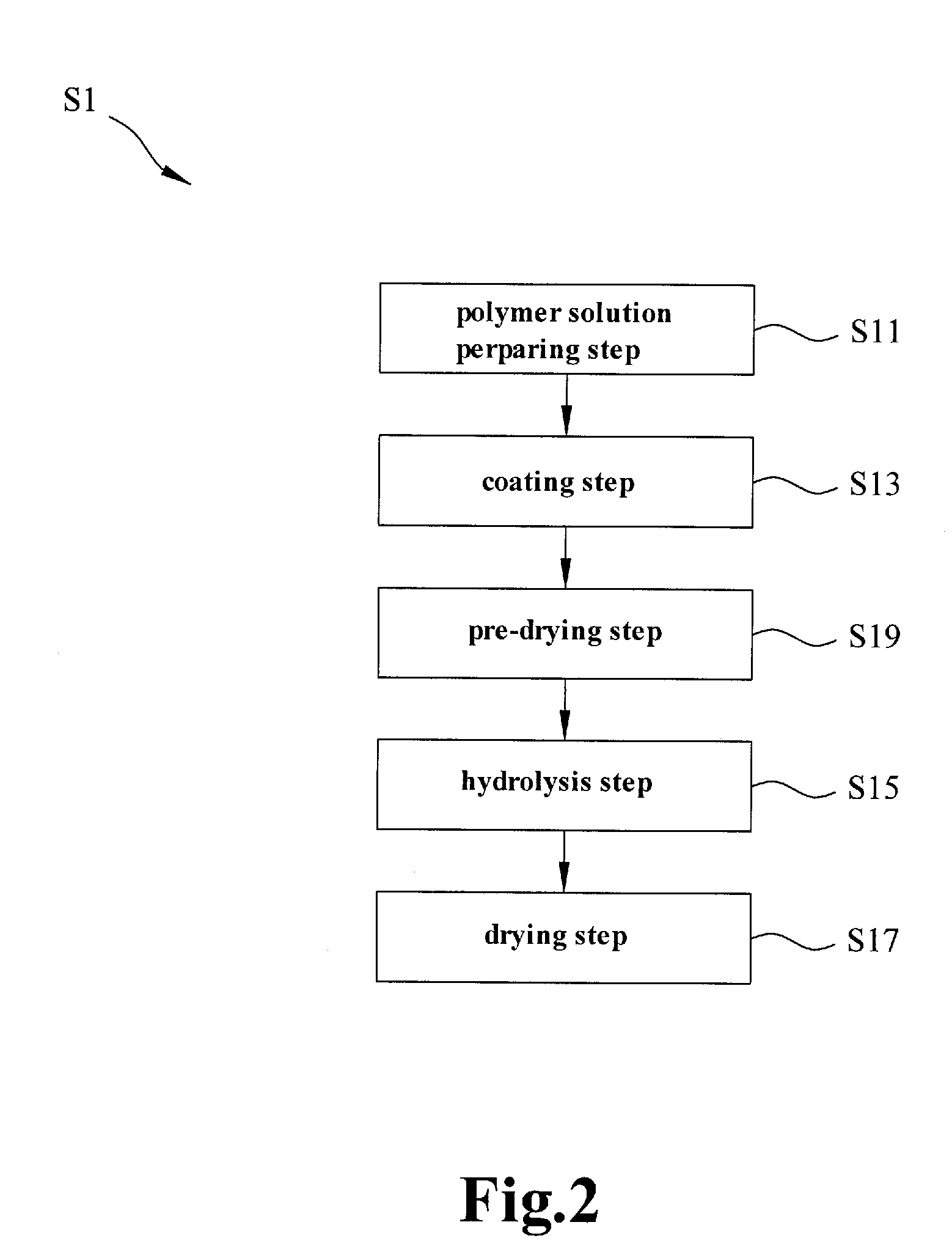
[0040]Experimental Example 1 describes manufacturing the ceramic particles by hydrolysis, wherein the ceramic particles and a polymer material are formed as a continuous phase and fill into the micro holes of a fabric support backbone structure. Takes polyvinylidene fluoride 6 wt % to dissolve in acetone with purity 99% firstly, maintains 4 hours at 60° C., and then add tetraethyl orthosilicate 2.5% and 5%, and 1 ml ammonia 28% serving as the catalyst to form the polymer solution after lowering the temperature to the room temperature. Stir 20 minutes to 1 hour to cause the polymer solution as slurry. Then coat the polymer solution dissolved and stringed uniformly on polyethylene or polypropylene fabric base material, and then a membrane predecessor is formed after the acetone vaporizes naturally. Put the membrane predecessor into super pure water 10 second to 1 minute to hydrolyze. A porous ceramic-polymer composite membrane which can be used to an electrochemical separation membran...

experimental example 2

[0042]Experimental Example 2 describes manufacturing the ceramic particles by hydrolysis, wherein the ceramic particles and a polymer material are formed as a continuous phase and fill into the micro holes of a fabric support backbone structure. Take polyvinylidene fluoride 6 wt % and polyethylene cellulose 0.5% to dissolve in acetone 90 wt % and pure water 3.5% firstly, maintains it for 4 hours at 60° C., then add tetraethyl orthosilicate 2.5% and 5%, and 1 ml ammonia 28% serving as the catalyst to form the polymer solution after lowering the temperature to the room temperature, and stir for 20 minutes to 1 hour to cause the polymer solution as slurry. Then, coats the polymer solution dissolved and stringed uniformly on polyethylene or polypropylene fabric base material, and then a membrane predecessor is formed after the acetone vaporizes naturally. Put the membrane predecessor into super pure water 10 second to 1 minute to hydrolyze. A porous ceramic-polymer composite membrane wh...

experimental example 3

[0044]The method and steps of Experimental Example 3 is similar to Experimental Example 2, the only difference is to coat the polymer solution dissolved and stringed uniformly on polyethylene or polypropylene porous membrane base material, and then a membrane predecessor is obtained after the acetone vaporizes naturally. Put the membrane predecessor into super pure water 10 second to 1 minute to hydrolyze. A porous ceramic-polymer composite membrane which can be used to an electrochemical separation membrane is obtained after drying, wherein the porous ceramic-polymer composite membrane has a thickness ranging 30˜40 μm.

[0045]Compare the cycle electrical properties at 5 C charge / discharge rate of the battery using the electrochemical separation membrane made from Experimental Example 3 of the present invention and the battery using commercial Celgard separation membrane at 55° C., and the comparing result is shown as FIG. 5. The result shows that the battery used the electrochemical ...


PUM

PropertyMeasurementUnit
porosityaaaaaaaaaa
thicknessaaaaaaaaaa
thicknessaaaaaaaaaa

Abstract

An electrochemical separation membrane and the manufacturing method thereof are disclosed. The method includes: a polymer solution preparing step to mix a polymer material, solvent and ceramic precursors thoroughly to form a polymer solution, wherein the polymer material and the ceramic precursors are dissolved uniformly in the solvent; a coating step to coat the polymer solution on a porous base material; a hydrolysis step to cause the porous base material coated with the polymer solution to contact an aqueous solution to hydrolyze the ceramic precursor into ceramic particles; and a drying step to remove the water and the solvent from the porous base material and in order to form the electrochemical separation membrane. The electrochemical separation membrane made of this method have better ion conductivity, interface stability and thermal stability based on the ceramic particles.

Description

CROSS-REFERENCE TO RELATED APPLICATION[0001]This application claims the priority of Taiwanese patent application No. 101120930, filed on Jun. 11, 2012, which is incorporated herewith by referenceBACKGROUND OF THE INVENTION[0002]1. Field of the Invention[0003]The present invention relates to an electrochemical separation membrane and the manufacturing method thereof, especially to the manufacturing method using ceramics precursors to produce ceramic particles by hydrolysis for forming a ceramic-polymer composite membrane having the inorganic particles distributed uniformly in polymer material, and having low internal resistance and high stability in circle charge / discharge.[0004]2. The Prior Arts[0005]The traditional secondary batteries, such as the nickel-cadmium batteries and the nickel-hydride batteries, have been replaced by a secondary lithium ion battery since the latter was presented to the public due to its advantages of high energy density and long lifespan. With the technol...

Claims


Application Information

Patent Timeline
Patent Type & Authority Applications(United States)
IPC IPC(8): B01D69/10B01D71/64B01D71/42B01D67/00B01D71/16B01D71/34B01D71/48B01D71/12B01D71/02B01D71/56H01M50/403H01M50/417H01M50/426H01M50/451H01M50/489H01M50/491
CPCB01D69/10B01D71/024B01D71/64B01D71/42B01D71/56B01D71/16B01D71/34B01D71/48B01D71/12B01D67/0079B01D67/0048Y02E60/10H01M50/403H01M50/446H01M50/417H01M50/451H01M50/491H01M50/489H01M50/426
Inventor WU, MARK Y.HSIEH, CHENG-YUCHANG, YUAN-HSINCHEN, JING-RUHSIEH, SHU-LING
Owner ENERAGE INC
Why Eureka
Try Eureka