Low Profile Apparatus and Method for Phototherapy

Active Publication Date: 2013-12-26
GRADIANT RES
View PDF5 Cites 14 Cited by
  • Summary
  • Abstract
  • Description
  • Claims
  • Application Information

AI Technical Summary

Benefits of technology

[0023]Example apparatus can be used to treat superficial tissue of a lumen or hollow organ with light, at irradiances that are ablative or coagulative, with substantial uniformity. They may include a light source selected such that its wavelength is advantageous for a desired tissue effect, such as ablation or coagulation to a target depth, denaturation, thermal modification of a tissue, and/or preferential injury to a target tissue structure. For example, they can be used to produce a uniform distribution of light at a surface

Problems solved by technology

A particular AR coating is effective over a limited range of wavelengths, consequently a handpiece may not be compatible with different light sources.
Simpler phototherapy handpieces may have no lens or one lens, although the light distribution may have poor uniformity.
Furthermore, because of the diameter of the optics and length of their housing, as well as other components, for example tissue cooling systems, these handpieces are bulky, heavy, and may be awkward to hold.
Operators frequently experience fatigue when performing long procedures.
These active cooling devices add cost and complexity, and in some cases use consumables, such as cryogen and gases.
Such procedures may be highly efficacious.
It is recognized that this directed output can readily damage the cornea or retina of the eye, and requires the use of eye protection by both operator and patient.
If light is accidentally emitted when directed towards the eye, the energy density at the eye will be low because of the scattered and highly divergent output of the handpiece.
However, the direction of overall light propagation remains orthogonal to the tissue surface in these diffusing devices, and the handpieces are therefore still bulky and large compared to the dimension of the irradiated area on the tissue surface, and consequently have the disadvantages of the previously described phototherapy handpieces.
Without active skin cooling, the TRIA is limited to use by people with light skin and without suntans.
The source array approach is currently limited to low power applications, however, such as biostimulation.
Other disadvantages of the source array approach are complexity, the need for electrical connection to each source, management of waste heat generated by the light sources in proximity to the treatment surface, and the potential hazards of electrical current in proximity to the treatment surface and of explosive failure of the light generating sources.
Therapeutic applications of the source array approach are limited by relatively low powers produced by the arrays.
These approaches are also significantly limited in output power.
Therefore, despite the numerous devices and methods for applying light to an area of tissue using handpieces, arrays, patches, and light guides, there remain substantial long-standing limitations.
The available devices for uniformly irradiating surface areas of tissue are large and bulky when capable of high power treatment.
Thin, flat, low profile de

Method used


Image

  • Low Profile Apparatus and Method for Phototherapy
  • Low Profile Apparatus and Method for Phototherapy
  • Low Profile Apparatus and Method for Phototherapy

Examples


first embodiment

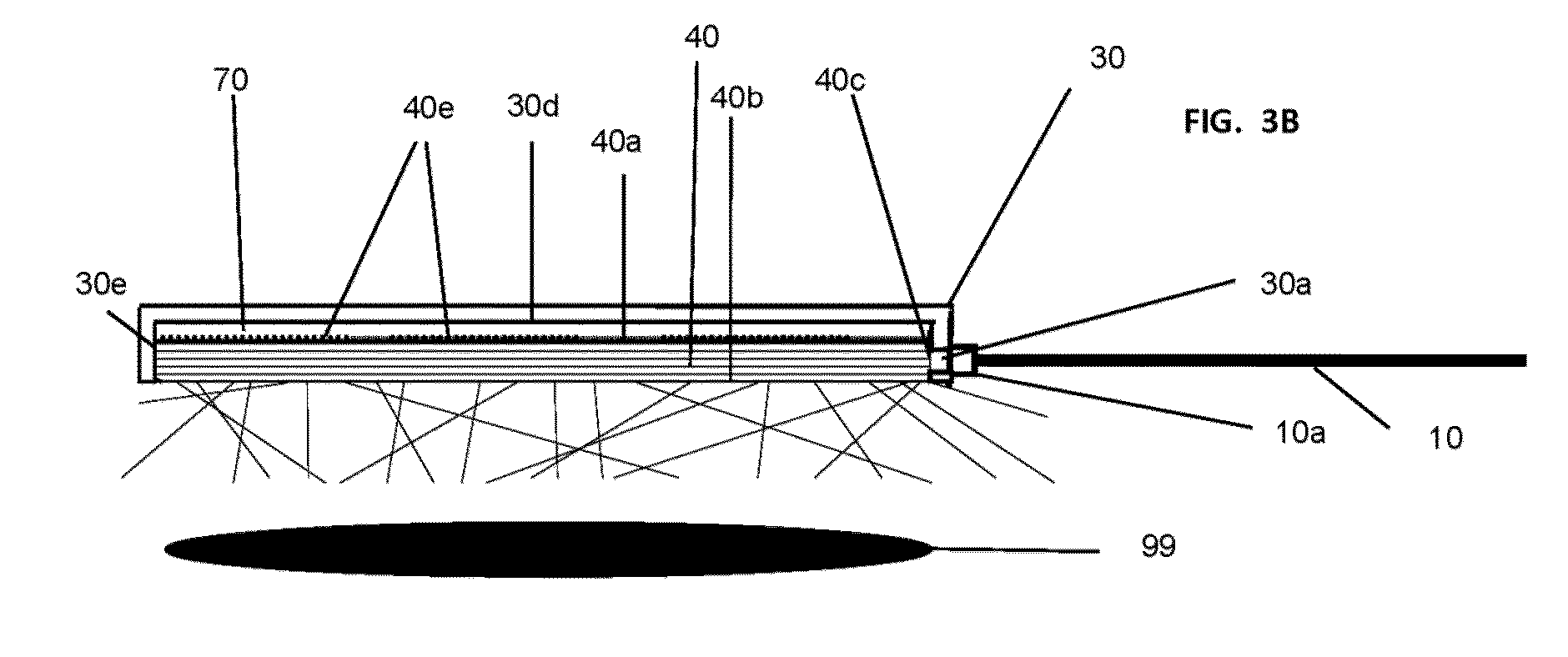
[0093]FIGS. 3A and 3B are schematic depictions of a simple first embodiment of the device of the invention.

[0094]FIG. 3A shows the circular contact surface (40b) of the optical assembly. The contact surface (40b) is flush with the edge surface (30e) of the device housing (30). An optical fiber (10) is attached at or near its light-emitting distal end to the housing (30) with a connector (10a). The proximal end of the optical fiber is attached to a laser or other light source (not shown).

[0095]FIG. 3B is a schematic cross-section depiction of the housing and optical assembly of this embodiment. Inside the housing (30) is a light guide plate (40) with proximal surface (40a), and distal or contact surface (40b). The housing (30) has an opening (30a) for entry of light from the optical fiber (10). The opening (30a) is positioned so that the output of the optical fiber is substantially transmitted to the light guide plate (40) through lateral input surface (40c) of said light guide plate...

second embodiment

[0110]FIGS. 5A and 5B are a schematic depiction of an embodiment of the invention that includes active cooling capability. FIG. 5A shows a circular light-emitting distal surface (60b) of a contact window. The distal surface (60b) is flush with the edge surface (30e) of the device housing (30). An optical fiber (10) is attached at or near its light-emitting distal end to the housing (30) with a connector (10a). The proximal end of the optical fiber is attached to a laser or other light source (not shown). The device also has inlet (20a) and outlet (20b) lines for flow of coolant fluid, connected to the housing (30) with inlet (20c) and outlet (20d) tubing connectors. The other ends of the coolant lines are connected to a cooling device (not shown). The cooling device may be a recirculating chiller with coolant fluid reservoir, or a cold air producing device.

[0111]FIG. 5B is a schematic cross-section depiction of the housing and optical assembly of this embodiment. Inside the housing ...

third embodiment

[0118]FIG. 6 is a schematic cross-section depiction of the housing and optical assembly of a third embodiment of the invention. As in the second embodiment, the third embodiment has active cooling capability, however the optical assembly has a minimal air gap between the light guide plate and a cooling layer window, to reduce scattering within the optical and thereby improve efficiency, compared to an optical assembly of the second embodiment.

[0119]Inside the housing (30) are a light guide plate (40), a cooling layer window (80), a cooling layer (50), and a contact window (60). The light guide plate (40) has a proximal surface (40a) and distal surface (40b). The housing (30) has an opening (30a) for entry of light from the optical fiber (10). The opening (30a) is positioned so that the output of the optical fiber is substantially transmitted to the light guide plate (40) through an input area (40c) on the lateral surface of said light guide plate. The openings of the housing for the...


PUM


Abstract

Disclosed herein are optical assemblies having thin, low profile shapes. These optical assemblies may be used with fiber coupled lasers and other light sources, including high power sources, to irradiate tissue at a wavelength suitable for inducing ablation or coagulation to a target depth, denaturation, thermal modification of a tissue, and/or preferential injury to a target tissue structure. Example optical assemblies can produce substantially uniform illumination patterns that are useful for treating superficial tissue, including the internal or luminal (e.g., esophageal) tissue. Some examples may have capability for cooling superficial tissue or skin, such as a detachable, reusable heat sink for active cooling without consumables, fluid pumps, or other cooling equipment.

Description

RELATED APPLICATIONS[0001]This application is a divisional of U.S. application Ser. No. 12 / 952,946, filed Nov. 23, 2010, which is a continuation-in-part of U.S. application Ser. No. 12 / 625,335, filed Nov. 24, 2009, which claims the benefit of U.S. Provisional Application No. 61 / 117,279, filed on Nov. 24, 2008. U.S. application Ser. No. 12 / 952,946 also claims the benefit of U.S. Provisional Application No. 61 / 264,161, filed Nov. 24, 2009. The entire teachings of the above applications are incorporated herein by reference.BACKGROUND OF THE INVENTION[0002]Phototherapy, defined herein as the use of light in the treatment of tissue in the human body, is a well established field of medicine. Light, defined as electromagnetic radiation of one or more wavelengths, may be used as the sole component of phototherapy, or phototherapy may involve the combination of light with drugs, dyes or other chemical agents, as well with radiofrequency, ultrasound, or other forms of energy. Phototherapy may...

Claims


Application Information

Patent Timeline
IPC IPC(8): A61B18/22
CPCA61B18/22A61B2018/2253A61B2018/2222A61N5/06A61N5/067
Inventor MCMILLAN, KATHLEENGUPTA, ANURAGMCGUIRE, JR., JAMES PATRICK
Owner GRADIANT RES
Why Eureka
Try Eureka