Conformal coating of cells for immunoisolation

a cell and immunoisolation technology, applied in the field of uniform cell coating for immunoisolation, to achieve the effect of compromising cell functionality

Active Publication Date: 2014-05-29
SERNOVA CORP
View PDF6 Cites 12 Cited by
  • Summary
  • Abstract
  • Description
  • Claims
  • Application Information

AI Technical Summary

Benefits of technology

[0015]Other advantages of the present invention include (1) overall decrease in encapsulated biomaterial graft volume, (2) minimal diffusion barriers for oxygen and nutrients through the capsules, (3) minimal delay in insulin responsiveness to glucose challenge, (4) minimal damage to the cell / cell cluster surface, allowing cell renewal and reorganization and (5) easy scale up from the bench to the clinic.
[0017]When cell clusters are added to the inner water phase, they flow coaxially within the water jet (the water phase is flowing around the cluster since the system is axially symmetric). In the focusing regions, the elongation component of the flow allows for easy separation of the cell clusters. Once the jet breaks up, the cell clusters are coated with a thin water layer that is proportional to the size of the jet. Cell cluster-containing capsules thus have a diameter that is proportional to the cluster size and the thickness of the capsule depends only on the external fluid dynamic conditions.
[0019]There are several parameters which need to be controlled with this method in order to achieve conformal coating of biomaterials, such as cell clusters, with a precise thickness of coating: (1) water dripping to jetting transition, (2) jet break-up into microliter droplets (for cell cluster-free water phase) and into single cell cluster-containing droplets (for cell clusters in water phase), (3) internal polymerization of the coating material after jet break-up and before purification, and (4) efficient purification of coated cell clusters from the oil phase and from biomaterial-free coating material.

Problems solved by technology

Surface tension between the water phase and the oil phase then triggers a Rayleigh-Plateau instability between the two phases that ultimately causes water jet break-up into microliter droplets with a constant size that depends on (a) the geometry of the device, (b) the ratio between the water and oil flow rates, (c) the ratio between the water and oil viscosities, and (d) the surface tension between the two phases.

Method used


Image

  • Conformal coating of cells for immunoisolation
  • Conformal coating of cells for immunoisolation
  • Conformal coating of cells for immunoisolation

Examples


example 1

Computational Model

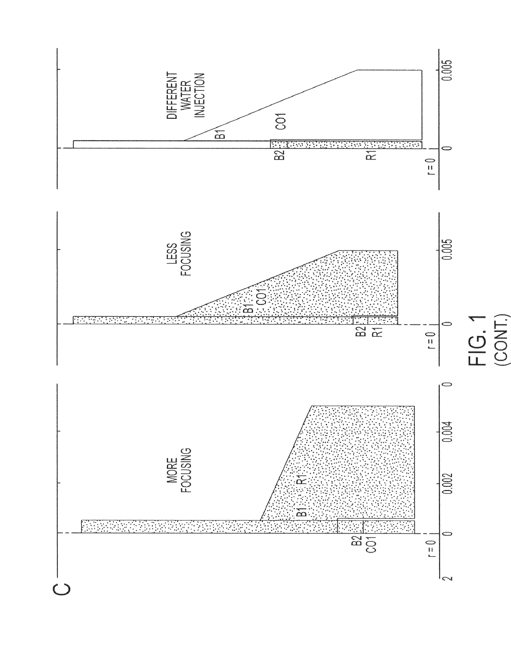
[0108]A computational model in Comsol Multiphysics (two-level set function of the chemical engineering modulus) has been developed to determine the effect of different geometrical parameters (“more focusing” and “less focusing” flow chamber and different injection points of the water phase into the oil phase) and fluid dynamic parameters (ratio between water and oil flow rates, ratio between water and oil viscosities, and interfacial tension between the two phases) on the transition from dripping to jetting of the water phase, the size of the final water jet, and the total stress acting in the center of the water jet.

[0109]A 2D axisymmetric geometry has been used with two different focusing settings: “more focusing” and “less focusing” and different water injection points. The mesh has been created by imposing a maximum size of the element in the central axis (r=0) equal to 10−5 m (FIG. 1C).

[0110]Table 1 shows the values of the different experimental fluid dynamic...

example 2

Flow Chamber Design and Realization

[0113]Flow chambers (with “more focusing” and “less focusing” geometry, different diameters of the co-axial chambers) have been designed and manufactured to experimentally test the effects of different geometries and different hydrodynamic parameters on islet encapsulation.

[0114]The flow chambers are characterized by a flow focusing region (“more” and “less” focusing) and a narrow straight channel down-stream.

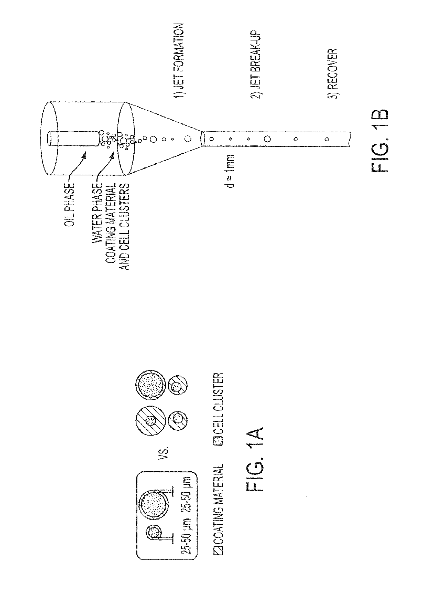
[0115]The water phase containing coating solutions and cell clusters is injected in the center channel by a catheter (FIG. 12A: 11, “more focusing” geometry) that is connected to the injection tube and pump through a male Luer integral lock ring (FIG. 12A: 10), and is focused in the main chamber (FIG. 12A: 3) into the narrow channel downstream (FIG. 12A: 4, 5, 7) from the main chamber by the co-flowing external stream of oil that is injected within the chamber through a lateral port (FIG. 12A: 9). Entrapped air is eliminated through a lateral ...

example 3

PEG Functionalization and Gelation

[0128]PEG gelation is achieved by cross-linking of PEG 8-arm 10 kDa, which has been functionalized with divinyl sulfone (PEG-dVS) or with maleimide (PEG-MAL), by addition of dithiothreitol (DTT) and by adjusting the pH from less than 6.5 to 7.4 using triethanolamine (TEA). Gelation of alternative non PEG-based hydrogels (for example, VLVG) is achieved by cross-linking of monomers that have been functionalized with divinyl sulfone (dVS) or with maleimide (MAL) by addition of dithiothreitol (DTT), and by adjusting the pH from less than 6.5 to 7.4 using triethanolamine (TEA).

[0129]A schematic on PEG functionalization with dVS (greater than 90%) by Michael type addition of dVS in the presence of NaH (1) is shown in FIG. 13.

[0130]In order to be able to image PEG gel by fluorescence microscopy, we labeled PEG-dVS with fluoresceinamine by Michael type addition in a sodium carbonate buffer (ibis) (FIG. 14).


PUM

PropertyMeasurementUnit
diameteraaaaaaaaaa
focusing angleaaaaaaaaaa
diameteraaaaaaaaaa

Abstract

Hydrodynamic methods for conformally coating non-uniform size cells and cell clusters for implantation, thus preventing immune rejection or inflammation or autoimmune destruction while preserving cell functionality. A method for conformally coating cells and c clusters with hydrogels that are biocompatible, mechanically and chemically stable and porous, with an appropriate pore cut-off size. The methods of the invention are advantageously reproducible and result in a relatively high yield of coated versus non-coated cell clusters, without compromising cell functionality. Conformal coating devices configured to perform the methods of the invention, methods of optimally utilizing said devices and purifying the coated islets, and coated biomaterials made by said methods.

Description

BACKGROUND[0001]Cell encapsulation is a promising strategy for immunoisolating single cells and cell clusters and thus preventing any immune response that would compromise the functionality of the cells upon implantation. Bio-encapsulation has been extensively employed for novel therapeutic trials in the fields of diabetes, hemophilia, cancer and renal failure. However, most trials have not been fully successful for a combination of reasons:[0002]lack of reproducibility in encapsulation and cell isolation methods;[0003]lack of suitable encapsulation materials which should be biocompatible, mechanically and chemically stable, and have an appropriate pore cut-off size to allow nutrient and by-product flow in and out of the capsule while protecting encapsulated biomaterial from immune system effects;[0004]production of non-uniform or non-conformally coated capsules (affecting oxygen and nutrient diffusion through the capsule and therefore encapsulated cell viability);[0005]inability to...

Claims


Application Information

Patent Timeline
Patent Type & Authority Applications(United States)
IPC IPC(8): A61K35/39
CPCA61K35/39A61K9/0019A61K9/0024A61K47/10A61K9/008A61K9/06A61K9/2018A61K9/2027A61K9/2054A61K9/2059A61K9/4858A61K9/4866C12N5/0012A61L27/34A61L27/3604A61L27/3683A61L2420/02
Inventor HUBBELL, JEFFREYTOMEI, ALICE
Owner SERNOVA CORP
Why Eureka
Try Eureka