
Scalable processing of nanocomposites using photon-based methods

a nanocomposites and photon-based technology, applied in the direction of liquid/solution decomposition chemical coating, nuclear engineering, transportation and packaging, etc., can solve the problems of limiting the scale, random distribution of nanoparticles, and not allowing the nanoscale patterning of preexisting nanofeatures within a matrix, or the creation of more complicated nanostructures such as core-shell nanoparticles

Inactive Publication Date: 2014-10-09
THE JOHN HOPKINS UNIV SCHOOL OF MEDICINE
View PDF3 Cites 14 Cited by
  • Summary
  • Abstract
  • Description
  • Claims
  • Application Information

AI Technical Summary

Benefits of technology

The present invention provides methods for creating nanocomposites with specific functional behaviors in large volumes of materials. These methods involve contacting an optically transparent substrate with an organometallic metal precursor compound and a photocatalytic decomposable metal oxide precursor compound, and then selectively exposing certain areas of the substrate to a laser beam. This process results in the formation of nanoparticles with a metal core and a metal oxide shell in the exposed areas, creating a nanocomposite with improved functional properties.

Problems solved by technology

The polymer nanocomposites produced with these methods often result in a random distribution of nanoparticles, rods, cubes, etc. throughout the bulk of the polymer.
However, the prior art processes to date utilize longer laser exposure times and are limited in scale due to diffraction limited optical effects and result in incorporation of nanoparticles randomly throughout a substrate and do not allow for the nanoscale patterning of preexisting nanofeatures within a matrix or for the creation of more complicated nanostructures such as core-shell nanoparticles.

Method used


Image

  • Scalable processing of nanocomposites using photon-based methods
  • Scalable processing of nanocomposites using photon-based methods
  • Scalable processing of nanocomposites using photon-based methods

Examples


example 1

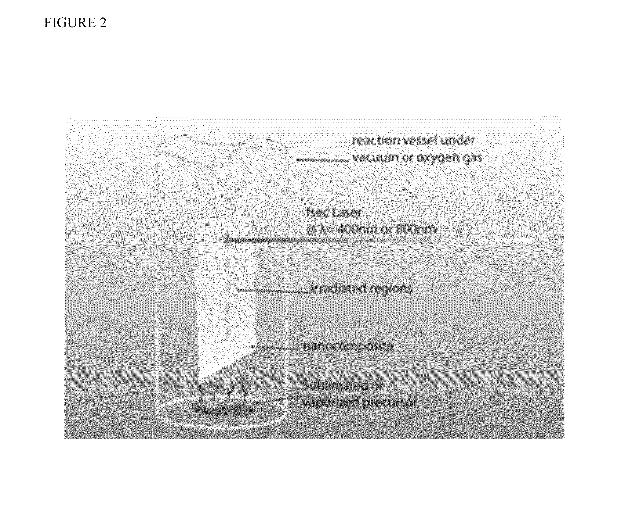
[0033]The starting material for the first series of experiments was a silver polymer nanocomposite synthesized using a modified CVD nanoinfusion process. This process begins by placing a FEP polymer film in a reaction vessel with vinyltriethylsilane-(hexafluoroacetylacetonate)silver(I) [Ag(CF3COCHCOCF3)(C8H18—Si)], an organometallic silver precursor. This was performed in a glove box under an argon atmosphere in order to keep the silver precursor from reacting with oxygen in air. The bottom portion of the reaction vessel, which contained the silver precursor, was then placed in a dewar containing liquid nitrogen. After the precursor was frozen, the vessel was evacuated to a vacuum level of 100 mTorr. The vessel was then sealed, removed from the liquid nitrogen dewar, and allowed to return to room temperature (20° C.). This process was performed two more times to sufficiently remove any air trapped within the liquid precursor. Finally, the evacuated reaction vessel was placed in an o...

example 2

[0035]A similar procedure was also used to obtain a tungsten oxide nanocomposite. Using tungsten carbonyl [W(CO)6] as the organometallic precursor, the vessel was heated to 140° C. and held at that temperature for 3 hours to allow the tungsten carbonyl to sublimate and diffuse into the FEP polymer film. It was then heated to 165° C., the experimentally determined temperature at which tungsten carbonyl decomposed and held at that temperature for 2 hours, resulting in the nucleation of tungsten oxide nanoparticles within the bulk of the polymer film. This infusion process was performed twice to obtain a 2× WO3-FEP nanocomposite. The 2× WO3 nanocomposite was then placed in a reaction vessel with a small amount of the silver precursor described above. The vessel was evacuated and placed in an oven with an optical window and heated to 100° C. After 45 minutes at 100° C., the sample was selectively irradiated with femtosecond laser pulses. For this processing, the laser pulses were unampl...

example 3

[0037]Two different materials systems (a 2× Ag-FEP nanocomposite and a 2× WO3 nanocomposite) were patterned using different temperatures and laser irradiation conditions. They were both characterized using UV / Vis optical spectroscopy in order to determine the changes to their optical properties as a result of processing and were also characterized using TEM microscopy in order to observe structural and size changes in the nanoparticles in the polymer films.

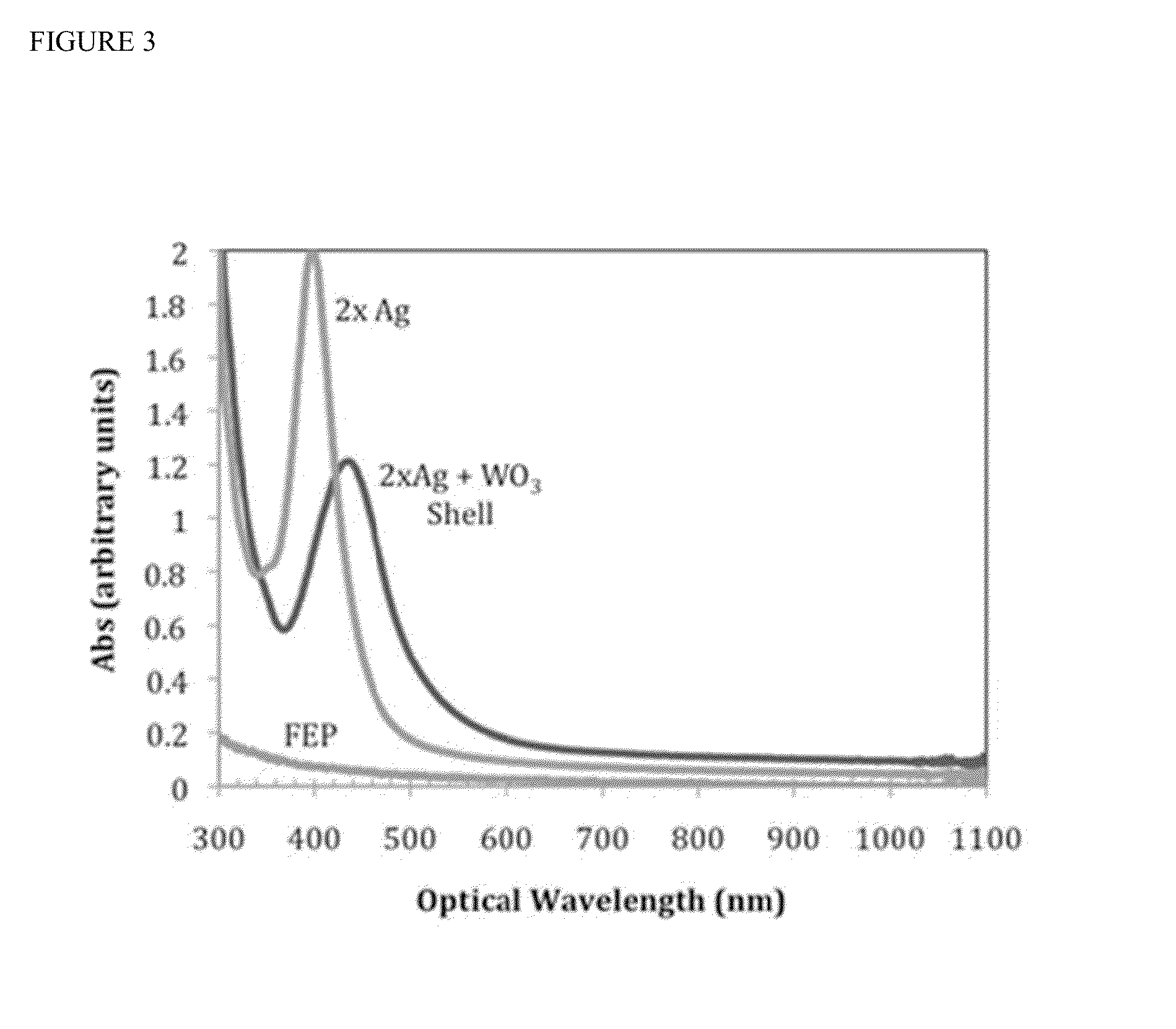
[0038]Optical Characterization. The UV / Vis spectrum for an unprocessed 2× Ag nanocomposite is shown in FIG. 3 and shows a large SPR located at an optical wavelength of 402 nm. After exposing the nanocomposite for 20 minutes to 90 μJcm−2 pulses at 400 nm, the nanocomposite displayed a 40 nm red shift in its SPR to 442 nm (also shown in FIG. 3). It should be noted that the 2× Ag nanoparticles absorb very strongly at 400 nm while the other materials in the nanocomposite system absorb very weakly, and therefore the silver nanoparticle...


PUM

PropertyMeasurementUnit
Timeaaaaaaaaaa
Pressureaaaaaaaaaa
Frequencyaaaaaaaaaa

Abstract

Using a modified CVD infusion process and femtosecond laser irradiation, the methods of the present invention demonstrate the ability to create core-shell nanoparticles of metal and metal oxide nanoparticles embedded within the bulk of an optically transparent substrate. Changes in the optical properties and changes in the structure, size, and shape of the nanoparticles were observed as a result of the methods. It was also observed that core-shell nanoparticles made using the inventive methods preferentially nucleated in the near surface region of the substrate, indicating a precursor-diffusion-dependent process for the nucleation growth of core-shell nanoparticles. With the use of optical masks and multiple precursor chemicals, the inventive methods make it possible to create nanoparticles or core-shell nanoparticles with drastically different compositions in close proximity to each other. Since the mechanism for precursor decomposition is limited to the surface of the nanoparticles within the substrate, it is possible to control the chemistry, size, and shape of nanoparticles within an optically transparent substrate on a nanoscale.

Description

BACKGROUND OF THE INVENTION[0001]Many polymer matrix nanocomposites are composed of a random distribution of nanoparticles within a solid polymer matrix. The material properties of these nanocomposites are determined by the size and type of nanofeatures, their distribution in the matrix, and their interaction with the bulk matrix material. Typically, these nanocomposites are engineered to have a specific property and are used as a coating to alter the material properties of a device or structure. They have been synthesized via CVD, thermolysis of chemical precursors, co-sputtering, evaporation, pulsed laser deposition, or by distributing nanoparticles within a liquid monomer solution that is subsequently polymerized. The polymer nanocomposites produced with these methods often result in a random distribution of nanoparticles, rods, cubes, etc. throughout the bulk of the polymer.[0002]It is desirable to be able to pattern polymer nanocomposites in order to tailor their material prope...

Claims


Application Information

Patent Timeline
IPC IPC(8): B05D3/00
CPCB05D3/207C23C18/06C23C18/08C23C18/1216C23C18/1233C23C18/1237C23C16/045C23C16/16C23C16/405C23C16/483C23C16/047C23C18/143C23C16/18C23C16/448
Inventor SPICER, JAMES B.DEJOURNETT, TRAVIS J.ZHANG, DAJIE
Owner THE JOHN HOPKINS UNIV SCHOOL OF MEDICINE
Learn More