Melt gasifier system

a gasifier and melt technology, applied in the direction of gasification process details, gas contaminants removal, inorganic chemistry, etc., can solve the problems of high energy consumption of gasifying agent generated electric power in an auxiliary facility including an oxygen plant, and the inability to filter fumes of incinerators which have proved unsatisfactory,

Inactive Publication Date: 2015-06-04
GUEH HOW KIAP
View PDF6 Cites 9 Cited by
  • Summary
  • Abstract
  • Description
  • Claims
  • Application Information

AI Technical Summary

Problems solved by technology

Other possible problems with regard to a known incinerator type of operation involves the filtration of incinerator fumes which have proved impractical because the odors generated are of a complex chemical nature not possible to filter out.
Other absorption and catalytic agents including masking agents used as counter-odorents have proved equally unsatisfactory.
However, consumption of the generated electric power in an auxiliary facility including an oxygen plant for producing such a gasifying agent is highly energy intensive.
If the temperature is not high enough, the outlet of the reactor may become blocked with unmelted metals.
Downdraft gasifier operation is generally unsuitable for fuels with high ash content because the high temperatures generated in the throat section of the hearth cause sintering of the ash into a slag which is difficult to remove and may cause functional problems in the system.
This upward flow of the vaporous products provides difficulty in the collection process and tends to harm the structure of the furnace due to the nature of the smoke products formed on the surfaces.
Furthermore, these gasification apparatus' operate at pressures exceeding ambient atmospheric pressure such that leakage of noxious fumes can be a problem.
This construction of a ram, while providing for the removal of material does not function in an efficient manner with regard to the burning of the product because the ram pushes away material which may contain some product not fully burned and thus reduces the efficiency of the process.
This can many times be a problem because of the nature of the material of the grate as well as the high temperatures involved in the process which could weaken the biomass suspension ability of the grate.
This is particularly true in large volume gasifiers where the weight of the biomass may become a problem on the grate structure.
This problem is particularly relevant when the grate is of a circular construction due to the nature of the high temperatures which occur at the support device for the grates and at the surface of the grate.
Possible problems involved in the known use of grate construction include the necessity for increasing the area of a circular grate each time the biomass handling capacity was to be increased which further increased the problem with regard to materials.
Likewise the large circular zone designs for grates and therefore may pose problems for combustion zones with scaling production capacities and requires the use of complex gas removal and ash removal mechanisms.
Processes for the production of a combustible gas from waste substances and other carbon-containing materials which are unsuitable or only inadequately suitable for direct combustion have long been known.
Various entrained flow gasifiers are known, such as U.S. Pat. No. 4,531,949, a common problem for instance, is that the biomass materials are not prepared in a sufficiently contained area to prevent discharging of odours into the surrounding environment.
Further inefficiencies arise when the biomass material is not prepared, gasified and subsequently completely combusted in a single environment with appropriate feedback and interaction between the various stages of the process.
It has been found that with increasing gas pressures and reduced reactor diameter, slag ingresses into the burner muffles.
This slag deflects the oxygen / coal flame towards the metallic muffle walls, which causes extremely high heat fluxes.
In combination with the higher overall surface temperatures steam blankets can be formed on the water cooling side, resulting in that locally no adequate cooling exists.
This in turn may result in that at such locations the metal of the membrane wall melts away.
The burner muffle of U.S. Pat. No. 4,818,252 is however vulnerable to slag ingress, when the gasification reaction is conducted under conditions wherein a thick layer of viscous liquid slag forms on the inside of the membrane wall.
In such a situation the slag will flow in front of the burner head and disturb the combustion.
However, this design is not adequate to cope with thick layers of slag.
This technology has major disadvantages leading to operation failures and limiting the availability of the technology as a whole.
The solidification leads to the formation of bridges and blocks the evacuation process.
During the operation of a stationary reactor, difficulties can arise—particularly when nozzles are arranged in the bottom area of the reactor for introduction of the carbon fuel and air instead of the lances described above.
Due to the gasification process, such nozzles tend to burn or wear off, or become corroded.
This naturally is costly in and of itself and additionally results in the loss of a great deal of operating time.
These same difficulties also ensue when repairing other damage such as wash-outs or corrosion of the fireproof cladding of the reactor, particularly in the area of the phase boundary.
Unfortunately, during cooling, formation of some zinc oxide also has been a partial result.
Apparently, some reversion to the oxide of zinc occurs with consequent loss of a portion of the desired carbon monoxide.
The so-formed zinc oxide is an undesirable product since the zinc oxide tends to form a coating around droplets of molten zinc, depositing as a “blue powder” in zinc collection chambers, leading to line plugging, and preventing subsequent reoxidation of the metallic zinc inside the droplets for reuse.
Excessive amounts of solid zinc oxide mixed with molten zinc create serious problems of material transport and handling of the molten zinc.
Blue powder has been a perennial problem in zinc handling for a long time.
Thus, in these patents, particularly U.S. Pat. No. 3,710,737, it is noted that carbon monoxide formation is undesirable, and although provision is made for a separate furnace or burner to combust any carbon monoxide present, carbon monoxide is stated to be a minor product of the reaction.

Method used


Image

  • Melt gasifier system
  • Melt gasifier system
  • Melt gasifier system

Examples


example 2

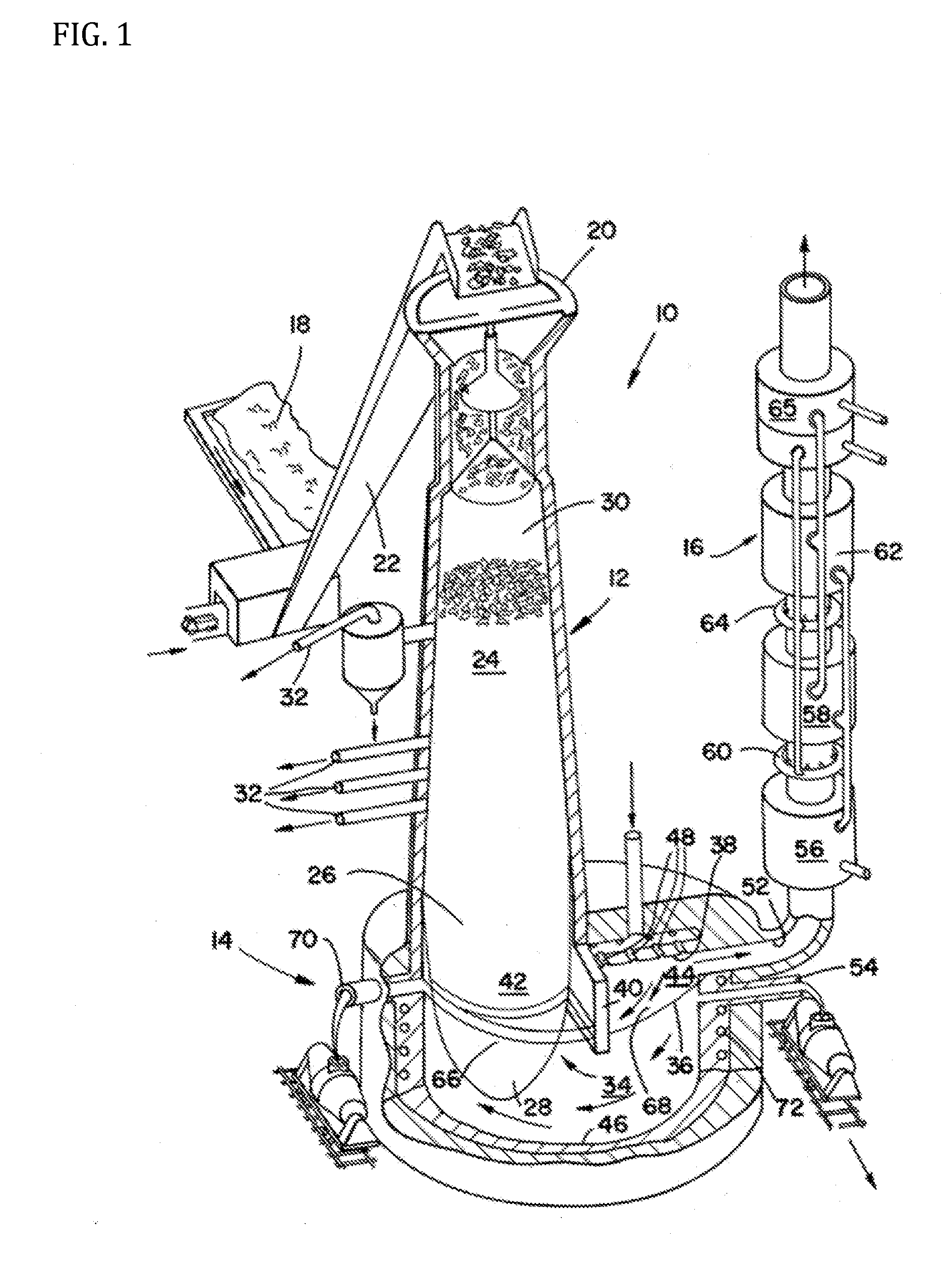
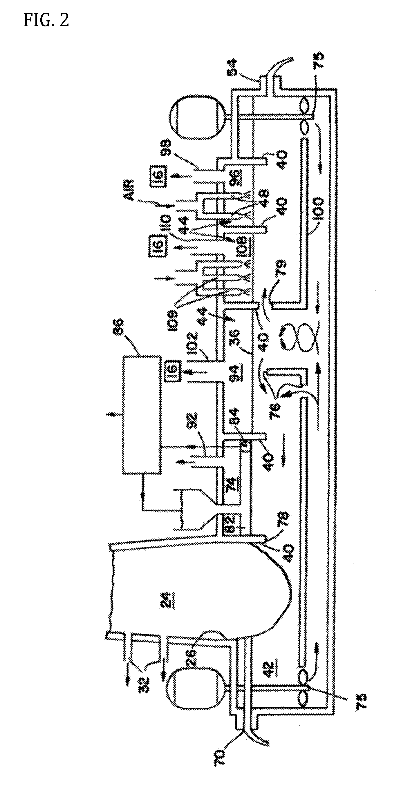
[0164]Referring now particularly to FIG. 2, there is illustrated therein a known embodiment implemented according to the present specification wherein the baffle means 40 defines in addition to the carbonization chamber 42 and the oxidation chamber means 44, a leaching chamber 74 for sulfur removal. The baffle means 40 serves to separate the leaching chamber 74 above the liquid level 36 from the carbonization chamber 42 and the oxidation chamber means 44, but allows flow of the liquid 34, for example, under the influence of mechanical stirrers 75, into the leaching chamber 74 from the carburization chamber 42 and out of the leaching chamber 74 and into the oxidation chamber means 44. Thus, liquid 34 which has both carbon and sulfur dissolved therein can enter the leaching chamber 74 via entrance means 76 and can leave the leaching chamber 74 via exit means 78 and can enter the oxidation chamber means 44 via oxidation entrance means 79.

[0165]A high basicity mixture of metal oxides is...

example 3

[0171]It is an object of this known example to provide an improved process for generating a low BTU gas from carbonaceous material. It is yet another object of the present specification to provide a process for heat generation from carbonaceous materials which obviates removal of pollutants formed in the combustion reaction. A particular object of the present specification is the provision of a process for partial oxidation of a carbonaceous material in a molten alkali metal salt medium for production of a gaseous effluent containing a high proportion of combustible gases, particularly carbon monoxide and hydrogen, such gaseous effluent then being adapted for further and complete combustion in a secondary reaction zone or combustor, to utilize the heat value of the gas.

[0172]In accordance with the broad aspects of the present specification, a carbonaceous material such as coal or a combustible waste material is introduced, together with a source of oxygen, suitably and preferably ai...

example 4

[0184]In this embodiment of a known bath gasifier configuration implemented according to the present specification, there is provided an apparatus for gasification of carbon (C) in the form of carbon, hydrocarbons and / or hydrocarbon compounds, comprising a reactor in which injection of carbon, oxygen gas and iron oxides takes place under the surface of the iron melt, and in which carbon is injected in stoichiometric excess in relation to the amount of oxygen in the form of oxide compounds in the melt, the reactor having a total inner pressure exceeding atmospheric pressure. The present specification is further characterized in that an exhaust gas pipe from the reactor is closely attached to a cooling device, which together with the reactor forms a sealed unit and in that a regulating valve for controlling and maintaining overpressure in the said unit is placed on the cold side of the cooling device.

[0185]FIG. 4 shows a reactor 1, lined and provided with a steel mantle, which during ...


PUM

PropertyMeasurementUnit
tilt angleaaaaaaaaaa
superficial gas velocityaaaaaaaaaa

Abstract

A method to perform gasification in a gasification reactor is having a molten metal material disposed within a refractory lined vessel of the gasification reactor for converting a feed into product syngas by contacting feed into melt. A melt is formed by inductive melting by one or more induction coil apparatuses. A feed is injected into contact with the melt to dissolve at least a portion of the feed into the melt. A refractory-lined vessel is tilted at a pre-determined tilt angle about a horizontal plane to cause the refractory-lined vessel to be tilted at said pre-determined tilt angle from said horizontal plane during a conversion of the feed into a product syngas. A molten slag material is directed to flow away from the refractory-lined vessel at a predetermined molten slag material flow rate and product syngas is directed to flow from the refractory-lined vessel to a powerplant for electric power generation, a first chemical catalytic reactor to chemically reform product syngas into a determined hydrocarbon product, a second chemical catalytic reactor to chemically reform product syngas into anhydrous ammonia product, a third chemical catalytic reactor to chemically reform product syngas into methanol product, or a combination thereof.

Description

[0001]The subject matter of the present specification relates to a method and apparatus for the gasification of cellulosic biomass, coal and other types of carbonaceous feed to produce low BTU syngas for downstream application such as electric power generation, or chemical upgrading into one or more determined syngas-derived product.DESCRIPTION OF THE RELATED ART[0002]The burning of refuse material in incinerators which use excess air to limit flame temperatures have produced large amount of effluent gases to be handled by gas cleaning equipment which must be of a tremendous size in order to handle the volume of gas generated. Other possible problems with regard to a known incinerator type of operation involves the filtration of incinerator fumes which have proved impractical because the odors generated are of a complex chemical nature not possible to filter out. Other absorption and catalytic agents including masking agents used as counter-odorents have proved equally unsatisfactor...

Claims


Application Information

Patent Timeline
Patent Type & Authority Applications(United States)
IPC IPC(8): C10J3/57C10J3/82C10J3/86
CPCC10J3/57C10J3/86C10J2300/1246C10J2200/15C10J2300/1656C10J3/82C10J2300/092C10J2300/0923C10J2300/093C10J2300/0946C10J2300/123C10J2300/1628C10K1/004Y02E20/18Y02E50/30
Inventor GUEH, HOW KIAP
Owner GUEH HOW KIAP
Why Eureka
Try Eureka