

Process for producing highly oriented graphene films
- Summary
- Abstract
- Description
- Claims
- Application Information
AI Technical Summary
Benefits of technology
Problems solved by technology
Method used
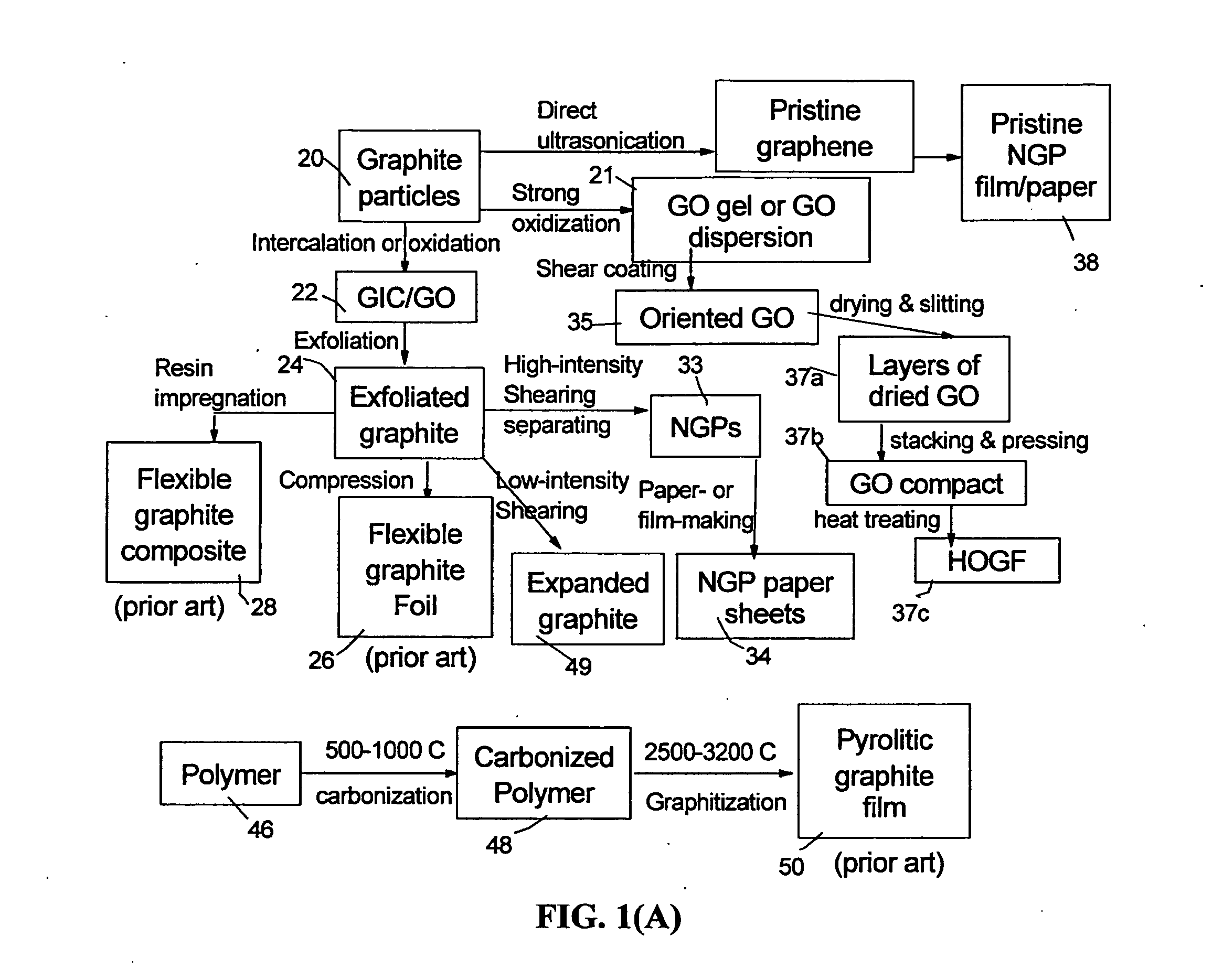
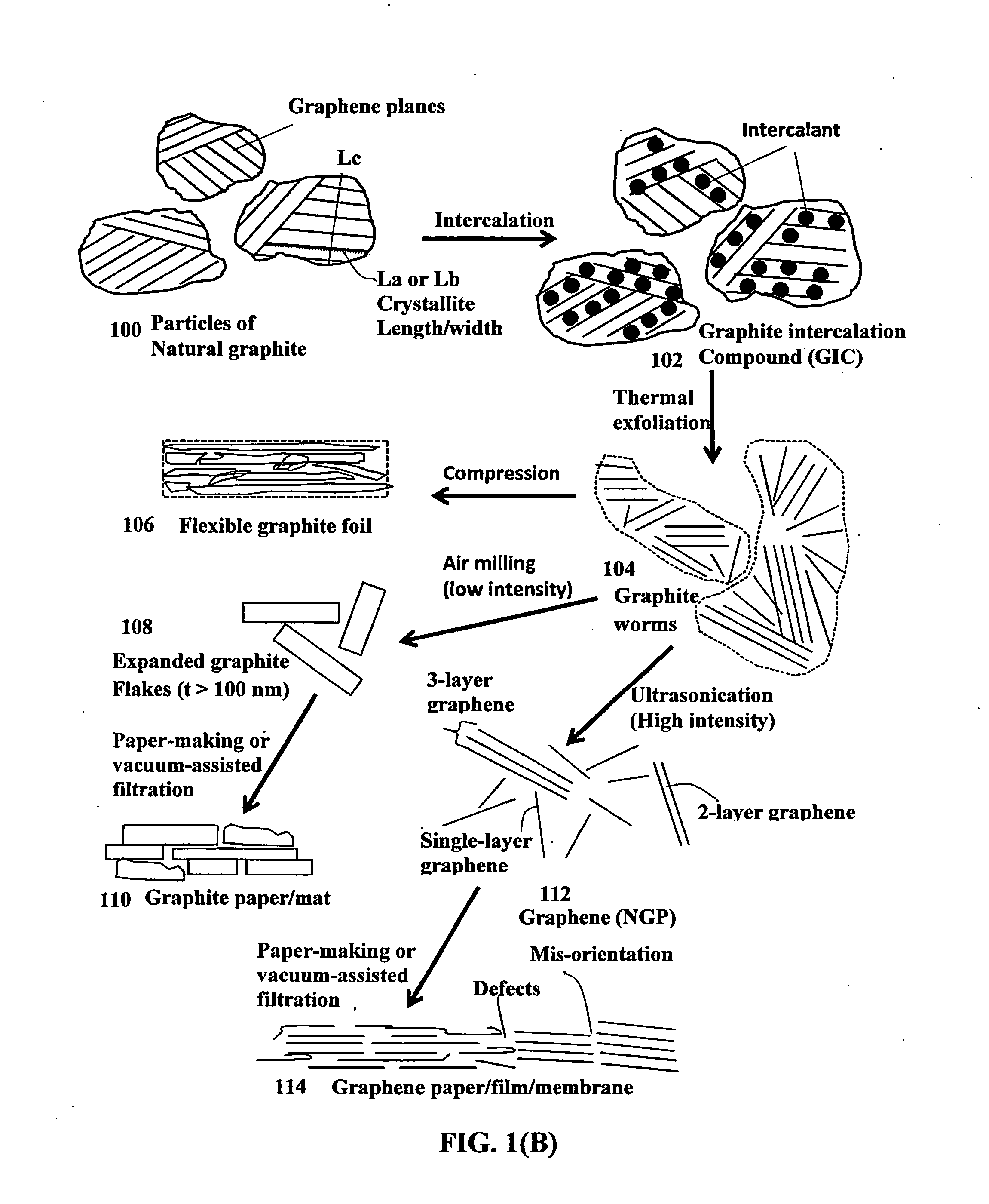
Image

Examples
example 1
Preparation of Discrete Nano Graphene Platelets (NGPs) which are GO Sheets
[0114]Chopped graphite fibers with an average diameter of 12 μm and natural graphite particles were separately used as a starting material, which was immersed in a mixture of concentrated sulfuric acid, nitric acid, and potassium permanganate (as the chemical intercalate and oxidizer) to prepare graphite intercalation compounds (GICs). The starting material was first dried in a vacuum oven for 24 h at 80° C. Then, a mixture of concentrated sulfuric acid, fuming nitric acid, and potassium permanganate (at a weight ratio of 4:1:0.05) was slowly added, under appropriate cooling and stirring, to a three-neck flask containing fiber segments. After 5-16 hours of reaction, the acid-treated graphite fibers or natural graphite particles were filtered and washed thoroughly with deionized water until the pH level of the solution reached 6. After being dried at 100° C. overnight, the resulting graphite intercalation comp...
example 2
Preparation of Single-Layer Graphene Sheets from Meso-Carbon Micro-Beads (MCMBs)
[0118]Meso-carbon microbeads (MCMBs) were supplied from China Steel Chemical Co., Kaohsiung, Taiwan. This material has a density of about 2.24 g / cm3 with a median particle size of about 16 μm. MCMB (10 grams) were intercalated with an acid solution (sulfuric acid, nitric acid, and potassium permanganate at a ratio of 4:1:0.05) for 48-96 hours. Upon completion of the reaction, the mixture was poured into deionized water and filtered. The intercalated MCMBs were repeatedly washed in a 5% solution of HCl to remove most of the sulphate ions. The sample was then washed repeatedly with deionized water until the pH of the filtrate was no less than 4.5. The slurry was then subjected ultrasonication for 10-100 minutes to produce GO suspensions. TEM and atomic force microscopic studies indicate that most of the GO sheets were single-layer graphene when the oxidation treatment exceeded 72 hours, and 2- or 3-layer g...
example 3
Preparation of Graphene Oxide (GO) Suspension and GO Gel from Natural Graphite
[0121]Graphite oxide was prepared by oxidation of graphite flakes with an oxidizer liquid consisting of sulfuric acid, sodium nitrate, and potassium permanganate at a ratio of 4:1:0.05 at 30° C. When natural graphite flakes (particle sizes of 14 μm) were immersed and dispersed in the oxidizer mixture liquid for 48 hours, the suspension or slurry appears and remains optically opaque and dark. After 48 hours, the reacting mass was rinsed with water 3 times to adjust the pH value to at least 3.0. A final amount of water was then added to prepare a series of GO-water suspensions. We observed that GO sheets form a liquid crystal phase when GO sheets occupy a weight fraction >3% and typically from 5% to 15%.
[0122]For comparison purposes, we also have prepared GO gel samples by extending the oxidation times to approximately 96 hours. With continued heavy oxidation, the dark-colored, opaque suspension obtained wit...
PUM
| Property | Measurement | Unit |
|---|---|---|
| Temperature | aaaaa | aaaaa |
| Temperature | aaaaa | aaaaa |
| Temperature | aaaaa | aaaaa |
Abstract
Description
Claims
Application Information