Novel nano-patterned thin film membranes and thin film composite membranes, and methods using same
a technology of nano-patterned thin film and composite membrane, which is applied in the direction of membrane technology, membrane technology, reverse osmosis, etc., can solve the problems of reducing membrane productivity and lifetime, affecting the continuous operation of polymeric membranes, and increasing operating and replacement costs
- Summary
- Abstract
- Description
- Claims
- Application Information
AI Technical Summary
Benefits of technology
Problems solved by technology
Method used
Image

Examples
example 1
Attenuated Total Reflectance-Fourier Transform Infrared
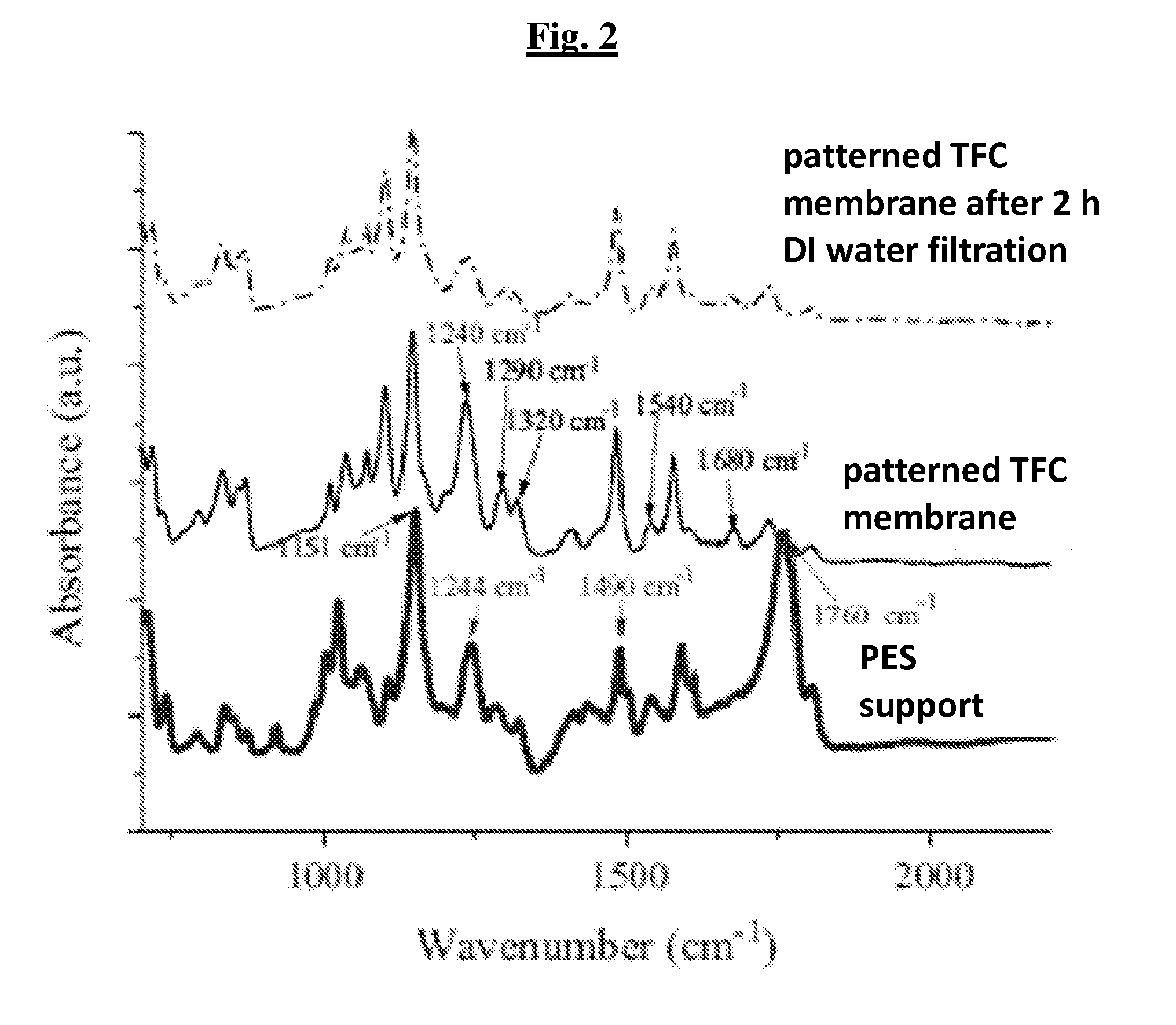
[0118]Attenuated Total Reflectance-Fourier transform infrared (ATR-FTIR) spectroscopy (Nicolet 6700 FT1R spectrometer, Thermo Fisher Scientific, equipped with a diamond ATR crystal) was used to characterize the polyamide barrier layers. Both the PES UF membrane support and the corresponding TFC membranes (after the IP process) were measured. Three replicate ATR-FT1R spectra were obtained for each membrane sample with each spectrum averaged from 128 scans collected from 700 to 2,200 cm−1 at 1 cm−1 resolution. Membrane samples were extensively rinsed and soaked in DI water for 24 h before they were dried in a vacuum oven prior to the ATR-FTIR measurements.
[0119]The FTIR spectra of the surfaces of the imprinted PES UF substrate with (patterned TFC membrane) and without (support only) the IP dense layer were compared in FIG. 2. The IR spectrum of a non-patterned TFC membrane was not included in the figure since it was identical to t...
example 2
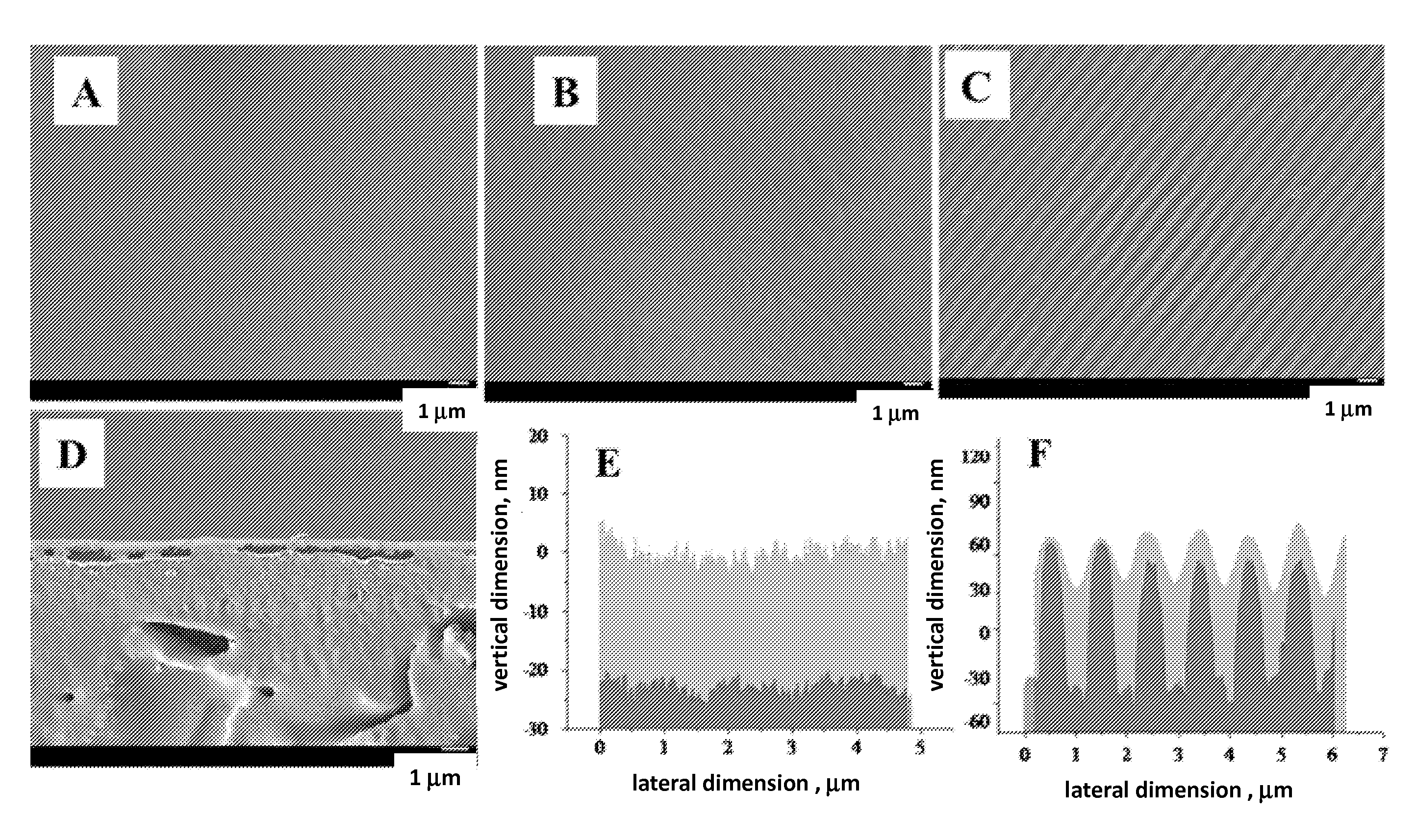
[0122]Surface topography and cross-sections of the membranes, before and after fabrication, were examined with a field-emission scanning electron microscope (FESEM, Zeiss, Supra 60) and an atomic force microscopy (AFM, Dimension 3100 AFM, Bruker). Membrane samples were dried in a vacuum oven prior to SEM measurements, and the membrane cross-sections were prepared using a microtome at −20° C., and coated with a 4.7 nm gold layer. All AFM measurements were performed with the tapping mode under ambient conditions using silicon cantilever probe tips (Veeco, RTESP).
[0123]FIG. 3 summarizes the morphological characterization of the patterned and non-patterned PES UF support membrane and the corresponding TFC membranes. The non-patterned UF membrane (FIG. 3A) had a smooth surface with an RMS roughness of less than 10 nm as determined from the AFM surface profile shown in FIG. 3C. After the imprinting process, periodic line-and-space grating patterns (FIG. 3D) wit...
example 3
Fabrication of the Patterned TFC Membrane
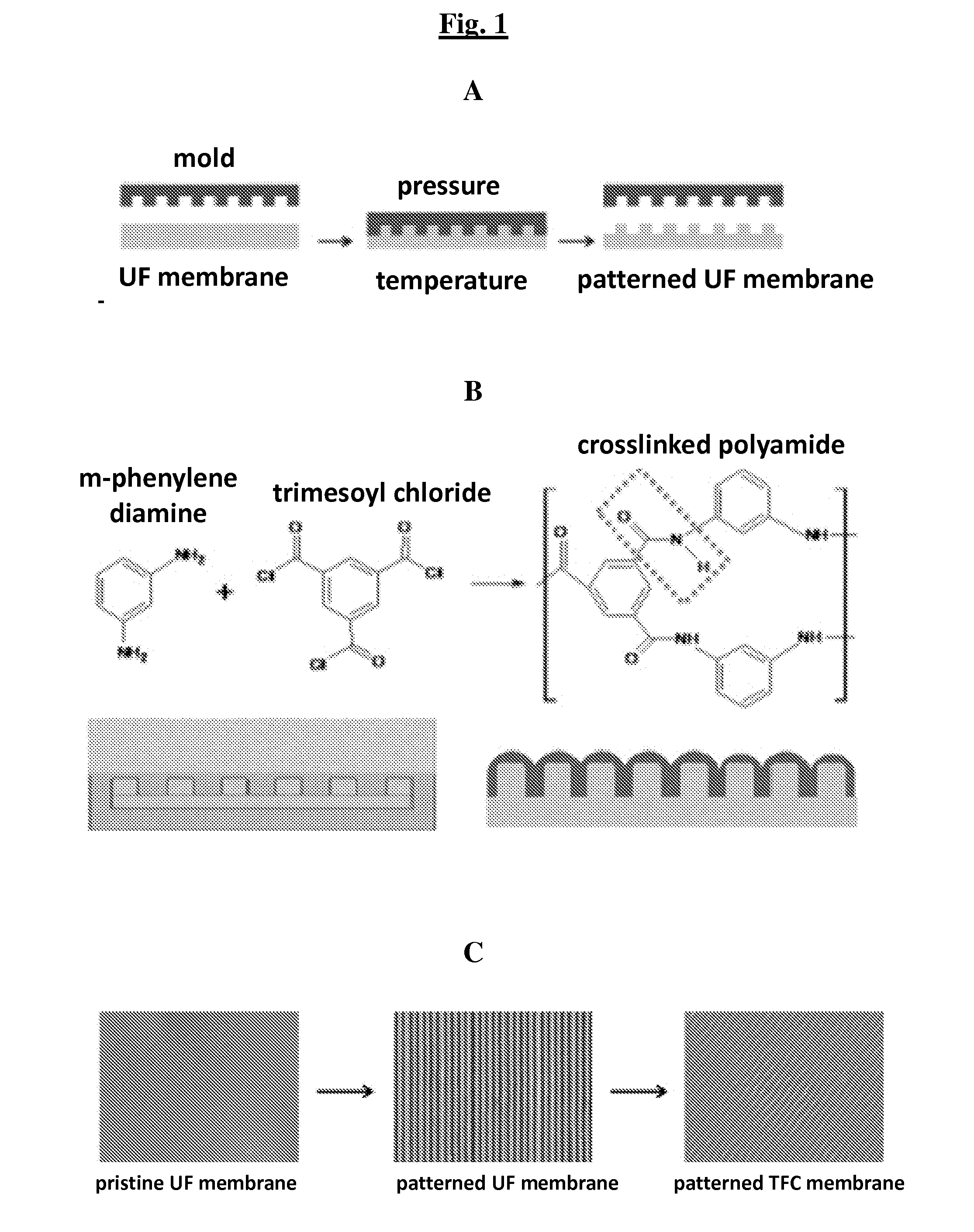
[0127]Patterned TFC membranes were fabricated using a two-step process that consisted of (1) nanoimprinting a PES support, and (2) forming a thin dense film atop the PES support using interfacial polymerization (IP) process. A commercial PES UF membrane (PW, GE Water and Infrastructure) with a nominal 30 kg / mol molecular mass cutoff (MWCO) was used as the substrate on which the polyamide thin film was hand-cast using IP.
[0128]Briefly, the NIL process was carried out in an Eitrie 3 (Obducat, Inc.) nanoimprinter, using a silicon mold containing parallel line-and-space gratings (a periodicity of 834 nm, groove depth of 200 nm, and a line-to-space ratio of 1:1). The Si mold surface was treated with a Piranha® solution (3:1 concentrated sulfuric acid to 30% hydrogen peroxide solution) prior to the imprinting. The NIL process was carried out at 120° C. with a pressure of 4 MPa for 180 s, and the mold was separated from the membrane samples at 40° C...
PUM
| Property | Measurement | Unit |
|---|---|---|
| Fraction | aaaaa | aaaaa |
| Fraction | aaaaa | aaaaa |
| Size | aaaaa | aaaaa |
Abstract
Description
Claims
Application Information
PatSnap Eureka turns technology decisions into work you can execute. Powered by our Innovation Knowledge Graph, it runs expert workflows across engineering, life sciences, materials and intellectual property. Get your review-ready output in minutes.


