Based on the location of the burners and the furnace exit, the air flow and
heat distribution are non-uniform.
However, one piece of SMR technology has been completely ignored where advancements are concerned.
That is, the refractory designs used in the construction of these units have remained stagnant for decades.
In particular, the
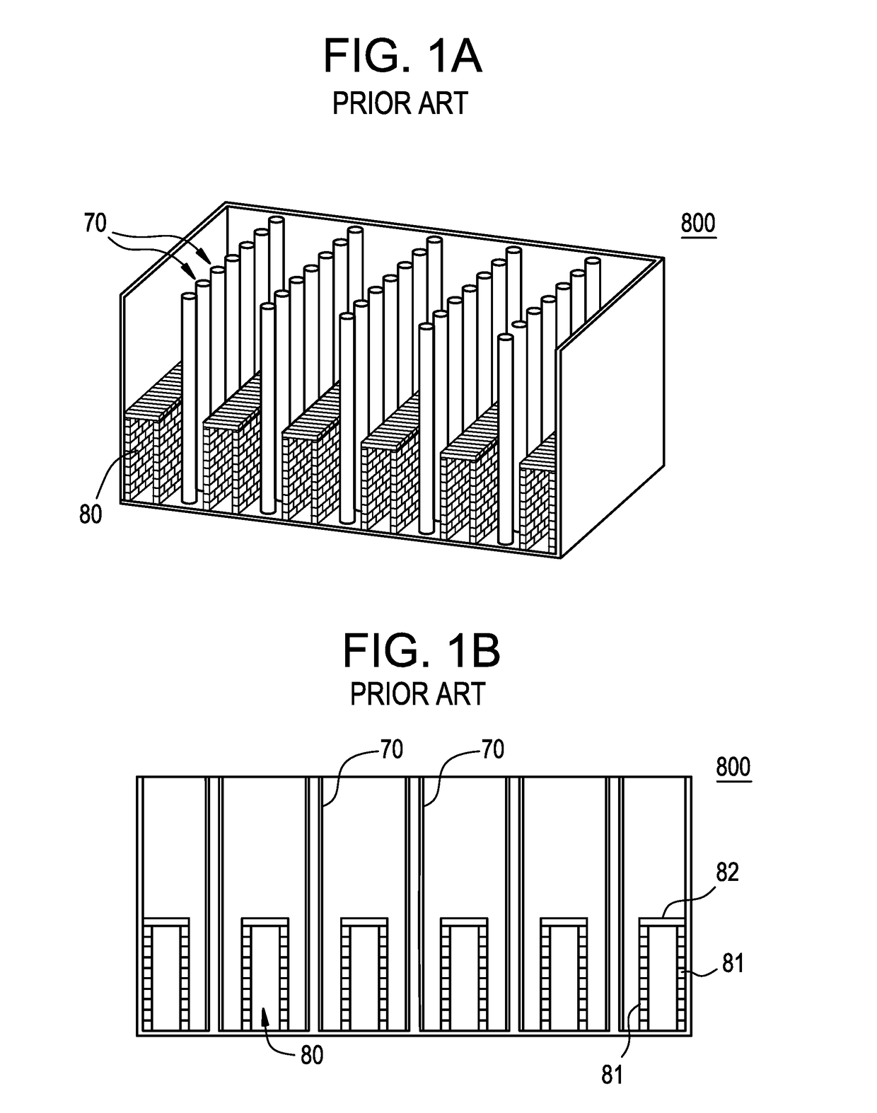
flue gas tunnels which transport
combustion gasses through the fired heaters have not been changed despite the clear need for improvement based on performance reliability issues.
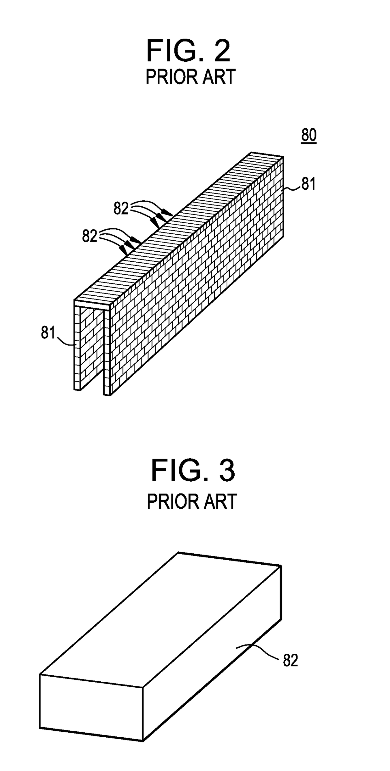
Historically, conventional tunnel walls 81 have been very prone to
mechanical failure under heat and over time.
The main
modes of failure for these
flue tunnels are related to refractory design, installation technique, mechanical abuse in service, and initial
material selection.
As a result, the reformer would not only experience reduced efficiency, but would also overheat the catalyst tubes near the exit, causing
premature failure to occur.
In this case, however, due to the presence of these large expansion gaps, every tunnel is actually made up of several large free-standing walls.
However simple the design may be, they serve an important purpose, because failed covers decrease the unit efficiency, cause
tunnel wall failure as they fall, and contribute to shorter tube life.
One of the current types of failures seen in the field is the collapsing of a section of lids, or all of the lids, over the entire length of the tunnel.
Once installed, the lids act as a beam, and a crack in the middle of the lid is often the result of the ratio between the span and the material thickness.
The cross-section (thickness) of the replacement lids is then increased, but after another campaign, the failure is typically even worse than before.
With many materials, the modulus of rupture (MOR) decreases significantly at higher temperatures, and it is possible to select a low grade refractory lid material whose MOR decreases at operational excursion temperatures to a point that even the mild stresses associated with the static load can result in failure.
One way the components can fail is if the
thermal expansion is not properly managed, resulting in excessive compressional force.
The component can also fail as a result of thermal stress that occurs as a result of any temperature differential incurred during operation, and is not limited to instances of large upsets.
Thermal
stress failure results when the
thermal expansion from one area of a component is different from another area resulting in a stress greater than the yield strength of the material.
If the temperature in the
convection section of the furnace is different than the temperature inside the tunnels, even for a short period of time, the potential for thermal stress is present.
In a situation where a very large number of the lids of a tunnel all failed during the same campaign without any of the walls collapsing, it is most likely that the mode of failure was thermal stress.
Creep of a lid will result in a “sagging” of the center span and will change the interaction force between the lid and the tunnel walls, and eventually lead to a failure.
Both instances are known to result in failure.
The effects of temperature and tunnel
mass are not limited to the internals of the furnace, but can also cause deformation of the supporting furnace structure, leading to a non-uniform furnace floor.
These wall sections act as a single body, and cannot accommodate any major dimensional change in the furnace floor.
Deformation of the supporting furnace structure will therefore result in the failure of a conventional tunnel.
This refractory
mortar also causes the wall sections to behave as a single body.
No furnace has a completely uniform temperature distribution, however, and at some point, differential
thermal expansion will occur across a wall section.
Since the
mortar joints are the weakest point on the wall, they crack to alleviate the stress.
The more
cracking that occurs in the mortared wall, the smaller the wall sections become, and the lower the stresses become in any one section.
Properly accommodating for thermal expansion is one of the most difficult aspects of any thermal application design.
The resulting trapezoidal shape is susceptible to buckling and collapsing.
This movement will crack the mortar, separate the walls from lids, and push the walls off of the IFB base; all of which lead to failure.
While traditional
tongue and groove brick design with a circular cross section (see, e.g., FIGS. 4 and 5) is somewhat effective in preventing
lateral movement, this arrangement does will not sufficiently arrest buckling, as the rotation of one block relative to the block below it will separate the tongue from the groove, allowing a full
system collapse (see, e.g., FIG. 15).
In addition to the above problems with the traditional wall design and components themselves, installing a conventional tunnel
system requires a number of skilled labor positions that are becoming increasingly challenging to fill, particularly for temporary needs.
This often creates a situation where the proper level of skilled labor is not available, and the overall quality of
resultant installed tunnel
system is compromised or the installation costs become higher than expected.
In some instances, a conventional tunnel system has simply operated for the full amount of its originally projected
life span, but due to short
time frame of a turnaround schedule the tunnel cannot be fully repaired or replaced and must continue to perform for an extended campaign.
The length of time and the
high skill level required to install a conventional tunnel system therefore becomes a cause for the reliability issues.
The full extent of damage that may be imparted to a tunnel system is often unknown prior to a turnaround, so a
maintenance engineering crew has only a few weeks to examine, design, and implement repairs that are meant only to keep the tunnel system operational until the next turnaround, where this kind of repair can be attempted again.
This is can be a very dangerous gamble for a
plant, based on the long
lead time and installation time associated with replacing the tunnels when a failure results in an unplanned outage.
The
extended time frame and high level of skill required for installation and repairs imparts undesirable variability in quality output for conventional tunnel systems.
Repairs that end up taking longer than the available window of
plant turnaround time are not a viable option, and often result in an undesirably extended tunnel campaign.


