
Method for treatment of metallic powder for selective laser melting

a laser melting and metallic powder technology, applied in the field of metal powder, can solve the problems of in-situ metal oxide phase formation, residual flux (slag) and/or correlated gas inclusions during slm processing, and are rather unfavorable, and achieve the effect of simple, effective and cost-effectiv

Inactive Publication Date: 2017-04-06
ANSALDO ENERGIA IP UK LTD
View PDF3 Cites 7 Cited by
  • Summary
  • Abstract
  • Description
  • Claims
  • Application Information

AI Technical Summary

Benefits of technology

The present invention provides a simple and cost-efficient method for improving SLM powder manufacturing, post-processing, and powder recycling. This method allows for easy modification of commercial standard alloys, reproducible manufacturing of components with SLM powders, and yielding particles with a defined compositional gradient. The method also allows for the manufacturing of derivatives of standard alloys in small batches with low cost impact. The method applies a specific FIC gas phase treatment to the base powder, which acts as in-situ flux during the SLM process, and a gas phase treatment can also be used to precipitate second phase particles onto the powder surface to improve mechanical properties of the manufactured component.

Problems solved by technology

Even that this dependency is less pronounced compared with the observed effect for standard welding techniques (TIG, MIG, MAG, LMF, etc.) it also contributes to the overall quality of weld classes achievable by SLM processing.d) Powder flowability which has an impact on the SLM processibility depends among others on the powder grain size distribution (see for example U.S. Pat. No. 5,147,448 A, describing techniques for producing fine metal powder), the powder particle shape and the overall humidity content in the powder batch.The latter is also a risk factor for in-situ metal oxide phase formation during laser melting within the SLM building of articles.
This could lead to residual flux (slag) and / or correlated gas inclusions during the SLM processing as a further disadvantage.
In document US 2013 / 0316183 A1 is therefore proposed to add commercially available flux products as separate fraction in a powder mix or as composite particles, but this is rather unfavorable due to the risk of significant flux residues and correlated slug inclusions, pore and crack formation in the SLM microstructure.f) The powder flowability is - in addition to the grain size distribution (see item d)—further depending on the particle surface condition.
Document U.S. Pat. No. 4,944,817 A discloses for example the use of coated or blended powder in selective beam sintering, document U.S. Pat. No. 7,384,447 B2 describes coated Ni-containing powders and complex methods for making such powders in an aerosol stream.Surface contaminants may also have an unpredictable influence on the final powder suitability for SLM manufacturing and the yielding SLM article quality (cracks, pores, oxide inclusions, eutectic formation etc.).
This is partly based on the absence of oxide films, which would otherwise negatively influence the stability of the weld bath (melting bed) zone.g) If certain elemental additions are needed today to adapt standard SLM powders of Ni base super alloys, for example additions of Nb, Ta, Ti and C for a controlled precipitation of finely granulated and distributed carbide phases, there are only insufficient and uneconomic methods available.First of all, the master melt of the standard alloy could be adjusted according to the needs.
Especially for low volumes this approach is cost-expensive.
Furthermore, it is particularly difficult to control the concentration of certain minor elements, notably if they are prone to oxidation or volatilization.The second approach would be to mechanically alloy two or more powder types of defined compositions in a predetermined ratio, but the resulting powder particle shape is a disadvantage.
Based on the spattered polygonal shape and wide size distribution, the yielding flowability is strongly inferior to the originally spherical powder fractions, which have been mechanically alloyed.
This has the following disadvantages:The un-melted powder in the powder bed is subjected to the reactive gas during at least a part of the build process, which can last several days.
This can result in strong change of powder chemistry and makes a reuse of the un-used powder difficult because of the contamination of the un-used powder with the reactive gas.h) SLM powder recycling is nowadays mainly based on a sieving treatment and might include a regular contribution of a variable fresh powder fraction ratio.
No additional methods are available to restore the chemical and physical properties of already used and herewith degenerated SLM powder in a reproducible way.
SLM operators have to replace the powder after a defined time, which leads to high cost impact on today's overall SLM processing costs.
This fact has additionally an unpredictable and not reproducible impact on the resulting SLM article quality.

Method used


Image

  • Method for treatment of metallic powder for selective laser melting
  • Method for treatment of metallic powder for selective laser melting
  • Method for treatment of metallic powder for selective laser melting

Examples


first embodiment

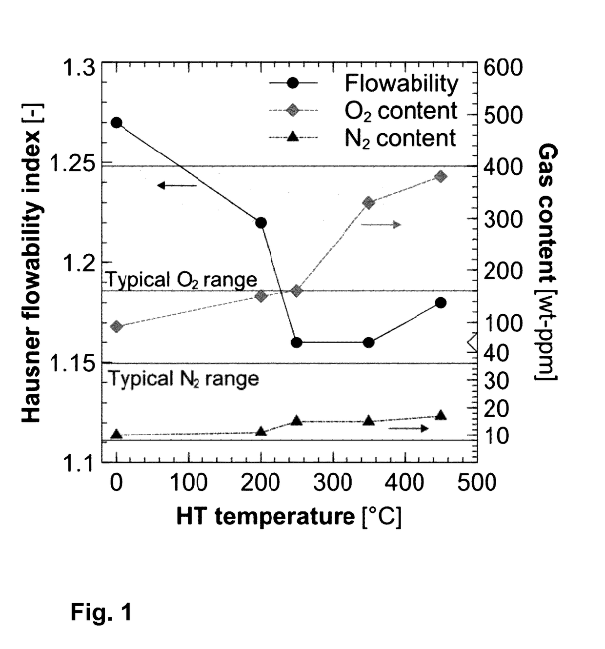
[0048]In a first embodiment, commercially available IN738 powder, stored in a small welded metal box (steel), was post heat treated at 500° C. / 1 h / Air and then a FIC cleaning with special parameters (p, T, t, gas composition) was done (=HT+FIC). The heat treatment results in at least partly oxidized powder and with the following FIC the “oxide / nitride skin” (including any other surface contaminations) is removed. The used specific FIC process regime results in a partial fluorisation of the Ni powder without unwanted secondary effects.

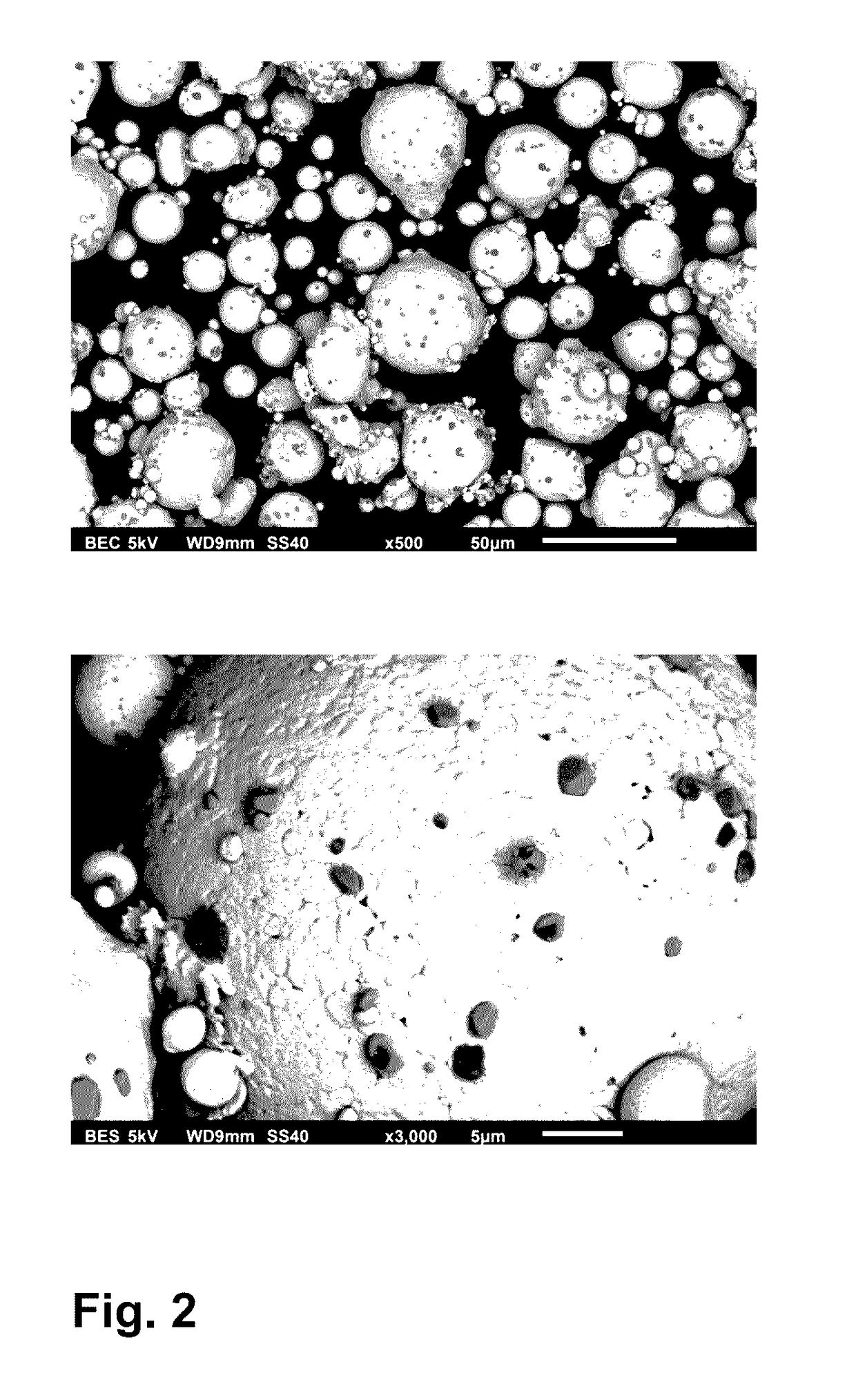
[0049]FIG. 2 shows the microstructure in SEM (Scanning Electron Microscope) with two different enlargement factors of the powder particles after such FIC treatment. Fine Fluoride particles (TiF4) could be clearly seen on the particle surface, the Ti content on the surface was increased. In addition, an enrichment of Nb, Ta and C, and a depletion of Al and Ti at least on the surface (achieving a concentration gradient) of the powder particles were invest...

second embodiment

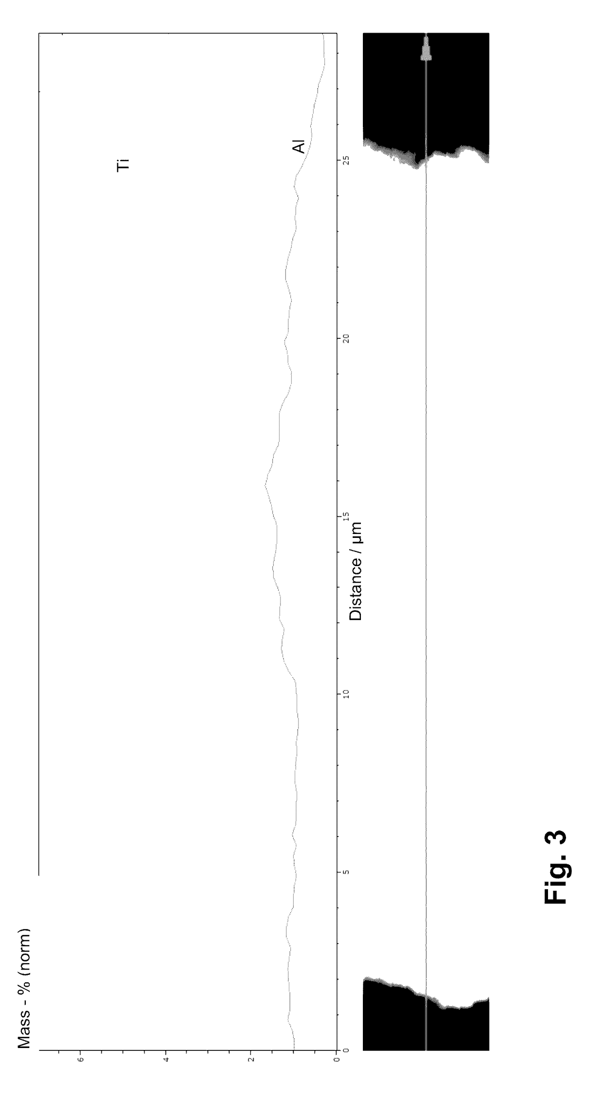
[0051]In a second embodiment IN738LC powder from a different supplier was heat treated under atmospheric conditions and then FIC treated and ball milled (BM). SEM and EDX (Energy Dispersive X-ray Spectroscopy) investigations show also a depletion of Al and Ti in the surface region, in the center were observed gamma prime particles (see FIG. 3). In addition, elongated needle like areas enriched in Ti, Nb, Ta could be seen, which would be typical for MC carbides (=HT+FIC+BM).

third embodiment

[0052]In a third embodiment IN738LC powder as delivered was FIC treated in a metal container with TBC powder, for example Y2O3 stabilized or pure ZrO2, on the bottom (=FIC+TBC).

[0053]With such variably treated powder a SLM processing (single layer processing, small grooves with width of 1 cm and depth of 80 pm) was done with the following parameters:

[0054]Laser power: 300 W

[0055]Scan speed: 1600 mm / s

[0056]Hatch distance: 0.07 mm

[0057]After cutting, grinding, polishing and etching (electrolytically H3PO4) of the SLM processed probes they were inspected by light microscopy and SEM of surface and microsections. The surface under the light microscope of the different probes showed no significant differences. SEM tests showed that the amount of surface oxides is varying according to the gas phase treatment. The FIC+TBC embodiment shows small and less oxides than the other ones and mostly dense oxide precipitations. In addition, no cracks were detected within the metallurgically investiga...


PUM

PropertyMeasurementUnit
chemical compositionaaaaaaaaaa
sizeaaaaaaaaaa
purityaaaaaaaaaa

Abstract

Methods are disclosed for treating a base materials in a form of metallic powder made of super alloys based on Ni, Co, Fe or combinations thereof, or made of TiAl alloys, which treated powder can be used for additive manufacturing, such as for Selective Laser Melting of three-dimensional articles.

Description

BACKGROUND OF THE INVENTION[0001]The present invention relates to metallic powder which is used for additive manufacturing processes, especially selective laser melting (SLM). More specifically, the invention refers to a method for treating powder made of Ni-, Co-, Fe-base super alloys or TiAl alloys which is used for manufacturing of three-dimensional articles, for example components for gas turbines, like blades or vanes. Said method can be applied for manufacturing of new powder, for a post conditioning of metallic powder or for recycling / refreshing of already used metallic powder.PRIOR ART[0002]There exists a demand in current state of the art for improvement of metallic SLM powder treatments because of the following limiting shortcomings:[0003]a) It is known that the SLM powder quality of different batches - even in the case of the same alloy and the same supplier—tend to show significant variations in the chemical composition and the flowability. This is based on the selected ...

Claims


Application Information

Patent Timeline
Patent Type & Authority Applications(United States)
IPC IPC(8): B22F1/02B22F9/04B22F1/00C23G5/00C23C14/08C23C16/30B33Y70/00B33Y10/00C23C16/44C23C16/32C23C16/40C23C16/34B22F9/16C23C14/06B22F1/14B22F1/145B22F1/16
CPCB22F1/02B22F2302/30B22F9/04B22F1/0003C23G5/00C23C14/08C23C14/0676C23C14/0664C23C14/0641C23C14/0635B33Y70/00B33Y10/00C23C16/4417C23C16/32C23C16/40C23C16/34C23C16/308B22F2302/45B22F2302/10B22F2302/20B22F2302/25B22F2302/15B22F9/16B33Y40/00B22F10/00B22F1/14B22F1/145B22F10/34B22F10/28B22F2998/10B22F10/73B22F1/16B22F1/00B22F2999/00B22F2201/11C23C16/00C23C14/00Y02P10/25B22F2009/0824B22F3/24B22F2003/241B33Y40/20B22F10/12Y02P10/20B22F9/082B22F10/20
Inventor STANKOWSKI, ALEXANDERENGELI, ROMAN
Owner ANSALDO ENERGIA IP UK LTD
Learn More