Continuous process for producing electrodes for supercapacitors having high energy densities

a supercapacitor and energy density technology, applied in the direction of reduction-oxidation hybrid capacitors, electric vehicles, transportation and packaging, etc., can solve the problems of low actual massloading of electrodes and apparent densities of active materials, poor structural integrity, and inability to provide high-capacity energy storage devices at the supercapacitor cell or pack level, etc., to achieve low overhead (ancillary component) weight and volume, high active material mass loading, and high volumetric capac a supercapacitor cell and supercapacitor cell and supercapacit supercapacitor cell technology, applied in the production process, which is applied in the field of supercapacitor cell and supercapacitor cell cell cell cell cell cell cell cell cell cell cell cell cell cell cell cell cell cell cell cell cell cell cell cell cell cell cell cell cell

Active Publication Date: 2017-04-13
NANOTEK INSTR GRP LLC
View PDF0 Cites 28 Cited by
  • Summary
  • Abstract
  • Description
  • Claims
  • Application Information

AI Technical Summary

Benefits of technology

[0024]The present invention provides a process for producing electrodes of a supercapacitor cell and further for producing the supercapacitor cell having a high active material mass loading, exceptionally low overhead (ancillary component) weight and volume (relative to the active material mass and volume), high volumetric capacitance, and unprecedentedly high volumetric energy density.

Problems solved by technology

However, there are several serious technical issues associated with current state-of-the-art ECs or supercapacitors:(1) Experience with ECs based on activated carbon electrodes shows that the experimentally measured capacitance is always much lower than the geometrical capacitance calculated from the measured surface area and the width of the dipole layer.
This disappointing performance is related to the presence of micro-pores (<2 nm, mostly <1 nm) and ascribed to inaccessibility of some pores by the electrolyte, wetting deficiencies, and / or the inability of a double layer to form successfully in pores in which the oppositely charged surfaces are less than about 1-2 nm apart.
In activated carbons, depending on the source of the carbon and the heat treatment temperature, a surprising amount of surfaces can be in the form of such micro-pores.(2) Despite the high gravimetric capacitances at the electrode level (based on active material weights alone) as frequently claimed in open literature and patent documents, these electrodes unfortunately fail to provide energy storage devices with high capacities at the supercapacitor cell or pack level (based on the total cell weight or pack weight).
This is due to the notion that, in these reports, the actual massloadings of the electrodes and the apparent densities for the active materials are too low.
In most cases, the active material mass loadings of the electrodes (areal density) is significantly lower than 10 mg / cm2 (areal density=the amount of active materials per electrode cross-sectional area along the electrode thickness direction) and the apparent volume density or tap density of the active material is typically less than 0.75 g / cm−3 (more typically less than 0.5 g / cm−3 and most typically less than 0.3 g / cm−3) even for relatively large particles of activated carbon.The low mass loading is primarily due to the inability to obtain thicker electrodes (thicker than 100-200 μm) using the conventional slurry coating procedure.
Contrarily, thicker samples tend to become extremely brittle or of poor structural integrity and would also require the use of large amounts of binder resin.
These problems are particularly acute for graphene material-based electrodes.
It has not been previously possible to produce graphene-based electrodes that are thicker than 150 μm and remain highly porous with pores remaining fully accessible to liquid electrolyte.

Method used


Image

  • Continuous process for producing electrodes for supercapacitors having high energy densities
  • Continuous process for producing electrodes for supercapacitors having high energy densities
  • Continuous process for producing electrodes for supercapacitors having high energy densities

Examples


example 1

Graphene from Carbon / Graphite Fibers

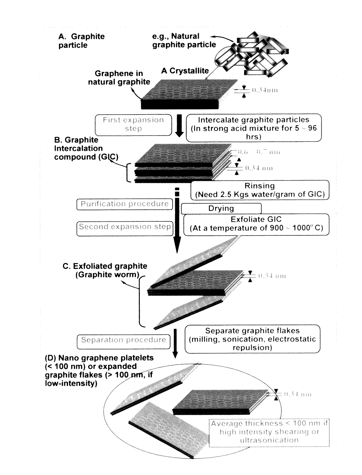
[0149]Continuous graphite fiber yarns were cut into segments of 5 mm long and then ball-milled for 48 hours. Approximately 20 grams of these milled fibers were immersed in a mixture of 2 L of formic acid and 0.1 L of hydrogen peroxide at 45° C. for 60 hours. Following the chemical oxidation intercalation treatment, the resulting intercalated fibers were washed with water and dried. The resulting product is a formic acid-intercalated graphite fiber material containing graphite oxide crystallites.

[0150]Subsequently, approximately ½ of the intercalated or oxidized fiber sample was transferred to a furnace pre-set at a temperature of 1,000° C. for 30 seconds. The compound was found to induce extremely rapid and high expansions of graphite crystallites. Approximately half of the as-exfoliated graphite fibers were subjected to de-oxygenation at 1,100° C. for 20 minutes in a nitrogen atmosphere to obtain reduced exfoliated graphite. A small amount each o...

example 2

Preparation of Graphene Oxide (GO) and Reduced Graphene Oxide (RGO) Nano Sheets from Natural Graphite Powder

[0154]Natural graphite from Huadong Graphite Co. (Qingdao, China) was used as the starting material. GO was obtained by following the well-known modified Hummers method, which involved two oxidation stages. In a typical procedure, the first oxidation was achieved in the following conditions: 1100 mg of graphite was placed in a 1000 mL boiling flask. Then, 20 g of K2S2O8, 20 g of P2O5, and 400 mL of a concentrated aqueous solution of H2SO4 (96%) were added in the flask. The mixture was heated under reflux for 6 hours and then let without disturbing for 20 hours at room temperature. Oxidized graphite was filtered and rinsed with abundant distilled water until neutral pH. A wet cake-like material was recovered at the end of this first oxidation.

[0155]For the second oxidation process, the previously collected wet cake was placed in a boiling flask that contains 69 mL of a concentr...

example 3

Preparation of Single-Layer Graphene Sheets from Meso-Carbon Micro-Beads (MCMBs)

[0159]Meso-carbon microbeads (MCMBs) were supplied from China Steel Chemical Co., Kaohsiung, Taiwan. This material has a density of about 2.24 g / cm3 with a median particle size of about 16 μm. MCMB (10 grams) were intercalated with an acid solution (sulfuric acid, nitric acid, and potassium permanganate at a ratio of 4:1:0.05) for 48-96 hours. Upon completion of the reaction, the mixture was poured into deionized water and filtered. The intercalated MCMBs were repeatedly washed in a 5% solution of HCl to remove most of the sulphate ions. The sample was then washed repeatedly with deionized water until the pH of the filtrate was no less than 4.5. The slurry was then subjected ultrasonication for 10-100 minutes to produce GO suspensions. TEM and atomic force microscopic studies indicate that most of the GO sheets were single-layer graphene when the oxidation treatment exceeded 72 hours, and 2- or 3-layer g...


PUM

PropertyMeasurementUnit
thicknessaaaaaaaaaa
thicknessaaaaaaaaaa
thicknessaaaaaaaaaa

Abstract

A process for producing a supercapacitor cell, comprising: (a) Continuously feeding a conductive porous layer to a cathode material impregnation zone, wherein the conductive porous layer contains interconnected electron-conducting pathways and at least 70% by volume of pores; (b) Impregnating a wet cathode active material mixture (containing a cathode active material and an optional conductive additive mixed with a liquid electrolyte) into pores of this porous layer to form a cathode electrode; (c) Preparing an anode electrode in a similar manner; and (d) Stacking an anode electrode, a porous separator, and a cathode electrode to form the supercapacitor, wherein the anode electrode and / or the cathode electrode has a thickness no less than 100 μm; and / or wherein the anode or cathode active material constitutes an electrode active material loading no less than 7 mg / cm2 in the anode or the cathode.

Description

FIELD OF THE INVENTION[0001]The present invention relates generally to the field of supercapacitors or ultracapacitors, and more particularly to the production processes for supercapacitor electrodes and cells.BACKGROUND OF THE INVENTION[0002]Electrochemical capacitors (ECs), also known as ultracapacitors or supercapacitors, are being considered for uses in hybrid electric vehicles (EVs) where they can supplement a battery used in an electric car to provide bursts of power needed for rapid acceleration, the biggest technical hurdle to making battery-powered cars commercially viable. A battery would still be used for cruising, but supercapacitors (with their ability to release energy much more quickly than batteries) would kick in whenever the car needs to accelerate for merging, passing, emergency maneuvers, and hill climbing. The EC must also store sufficient energy to provide an acceptable driving range. To be cost-, volume-, and weight-effective compared to additional battery cap...

Claims


Application Information

Patent Timeline
Patent Type & Authority Applications(United States)
IPC IPC(8): H01G11/50H01G11/36H01G11/46H01G11/02H01G11/58H01G11/86H01G11/26
CPCH01G11/50H01G11/86H01G11/36H01G11/46H01G11/02H01G11/58H01G11/26Y02E60/13H01G11/28H01G11/38H01G11/84Y02T10/70
Inventor ZHAMU, ARUNAJANG, BOR Z.
Owner NANOTEK INSTR GRP LLC
Why Eureka
Try Eureka