Decreased Photon Reabsorption in Emissive Quantum Dots

a quantum dots and reabsorption technology, applied in the field of nanostructure synthesis, can solve the problems of reduced photoconversion efficiency, undesirable red shift in peak emission wavelength (pwl), and limited method, and achieve long photoluminescence lifetimes

Inactive Publication Date: 2019-09-05
NANOSYS INC
View PDF0 Cites 9 Cited by
  • Summary
  • Abstract
  • Description
  • Claims
  • Application Information

AI Technical Summary

Benefits of technology

[0006]The present invention is directed to a nanostructure comprising a nanocrystal core and at least one thin inner shell, wherein the at least one thin inner shell has a thickness of between about 0.01 nm and about 0.35 nm, and wherein the nanostructure exhibits an effective Stokes shift of between about 25 nm and about 125 nm.

Problems solved by technology

When deployed at high optical densities, photon reabsorption can lead to reduced photoconversion efficiencies and undesirable red shifts in peak emission wavelength (PWL).
However, this method is limited by the large volume of the resulting quantum dots and negative effects of lattice strain for material systems with limited interfacial alloying between core and shell.
However, both strategies typically result in long photoluminescence lifetimes, which can cause lower photoluminescence quantum yield (PLQY) values in the presence of competitive non-radiative processes.

Method used


Image

  • Decreased Photon Reabsorption in Emissive Quantum Dots
  • Decreased Photon Reabsorption in Emissive Quantum Dots
  • Decreased Photon Reabsorption in Emissive Quantum Dots

Examples


example 1

Preparation of an InP / ZnS / ZnSe / ZnS (1 Equivalent Inner Shell)

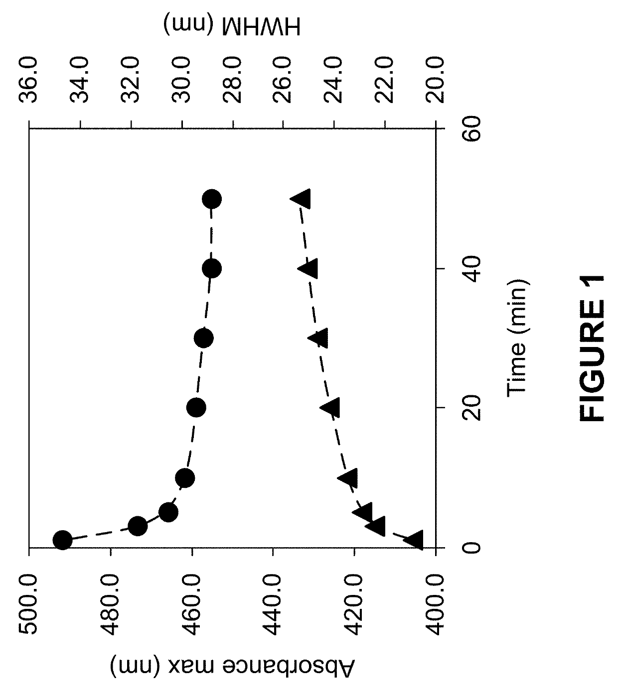
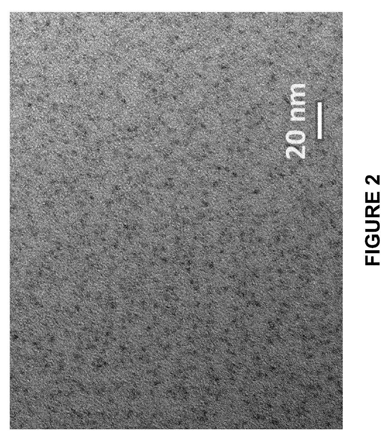
[0225]InP / ZnS core / inner thin shell nanostructures with 1 equivalent of inner ZnS shell were made by combining indium myristate (0.4 mmol), zinc oleate (0.4 mmol), dodecanethiol (0.4 mmol), and tris(trimethylsilyl)phosphine (0.4 mmol) in octadecene (32 mL). All materials were degassed under vacuum at room temperature and heated to 300° C. under an N2 atmosphere. Reaction progress was tracked by removing small aliquots and monitoring the UV-vis absorbance spectra. The reaction was stopped when the absorbance maximum (as shown in FIG. 1) was >430 nm by removing the heat source from the reaction. Once cooled to room temperature, the InP / ZnS core / inner thin shell nanostructure was precipitated with one volume of acetone and dispersed as the isolated material in hexane (5 mL). Transmission electron micrographs of the isolated InP / ZnS core / inner thin shell nanostructures are shown in FIG. 2. The reaction was scaled ten-fold and ...

example 2

Preparation of an InP / ZnS / ZnSe / ZnS (0.5 Equivalent Thin Shell)

[0228]InP / ZnS core / inner thin shell nanostructures with 0.5 equivalents of thin ZnS shell were made by combining indium myristate (0.4 mmol), zinc oleate (0.4 mmol), dodecanethiol (0.2 mmol), and tris(trimethylsilyl)phosphine (0.4 mmol) in octadecene (32 mL). All materials were degassed under vacuum at room temperature and heated to 300° C. under an N2 atmosphere. Reaction progress was tracked by removing small aliquots and monitoring the UV-vis absorbance spectra. The reaction was stopped when the absorbance maximum was >435 nm by removing the heat source from the reaction. Once cooled to room temperature, the InP / ZnS core / inner thin shell nanostructure was precipitated with one volume of acetone and dispersed as the isolated material in hexane (5 mL).

[0229]Further ZnSe and ZnS outer layers were grown as a secondary reaction on the isolated InP / ZnS core / inner thin shell nanostructure. Zinc oleate (6.2 mmol), lauric acid ...

example 3

Preparation of InP / ZnS Core / Inner Thin Shell Alternative Method

[0230]The effects of introducing a wide-band gap inner ZnS shell may also be observed following the growth of an thin ZnS shell in a secondary reaction on isolated and purified InP cores. Zinc oleate (5.4 mmol), lauric acid (5.4 mmol), and octadecene (11 mL) were combined in a flask. The reaction flask and contents were degassed under vacuum at room temperature and then heated under an N2 atmosphere. Isolated InP cores (0.14 mmol InP) were added when the temperature was between 85-145° C. A low-temperature reactive sulfur-precursor (equivalent amount to form 1 monolayer of ZnS) was added to the reaction flask. Following the formation of the inner thin ZnS shell layer, subsequent ZnSe and ZnS shell layers were grown as described in Example 1 via the addition of trioctylphosphine selenide and dodecanethiol in amounts equivalent to form 0-2.0 monolayers of ZnSe and 0-2.0 monolayers of ZnS. The final product was isolated by ...


PUM

PropertyMeasurementUnit
thicknessaaaaaaaaaa
thicknessaaaaaaaaaa
thicknessaaaaaaaaaa

Abstract

The invention is in the field of nanostructure synthesis. Provided are highly luminescent nanostructures, particularly highly luminescent quantum dots, comprising a nanocrystal core and a thin inner shell layer. The nanostructures may have an additional outer shell layer. Also provided are methods of preparing the nanostructures, films comprising the nanostructures, and devices comprising the nanostructures.

Description

BACKGROUND OF THE INVENTIONField of the Invention[0001]The invention is in the field of nanostructure synthesis. Provided are highly luminescent nanostructures, particularly highly luminescent quantum dots, comprising a nanocrystal core and a thin inner shell layer. The nanostructures may have additional outer shell layers. Also provided are methods of preparing the nanostructures, films comprising the nanostructures, and devices comprising the nanostructures.Background of the Invention[0002]Decreasing photon reabsorption in emissive quantum dots is critical to performance in applications such as quantum dot color filters. When deployed at high optical densities, photon reabsorption can lead to reduced photoconversion efficiencies and undesirable red shifts in peak emission wavelength (PWL).[0003]An alternative approach to reduce photon reabsorption is to increase the energetic separation between the absorbance and emission spectra, or the effective Stokes shift of the material. One...

Claims


Application Information

Patent Timeline
Patent Type & Authority Applications(United States)
IPC IPC(8): H01L33/06H01L33/00C09K11/08C09K11/62C09K11/56C09K11/54
CPCH01L33/06H01L33/005C09K11/0855C09K11/54C09K11/0811C09K11/56C09K11/62H01L33/502C09K11/70C09K11/02C09K11/565
Inventor JEN-LA PLANTE, ILANWANG, CHUNMINGLEE, ERNEST CHUNG-WEI
Owner NANOSYS INC
Why Eureka
Try Eureka