
Internal combustion engine and operating method of same

a technology of internal combustion engine and operating method, which is applied in the direction of machines/engines, combustion-air/fuel-air treatment, and separation processes, etc., can solve the problems of reducing the permeation flow through the membrane, affecting the effect of so2 gas, etc., to reduce pollution, prevent, and reduce the effect of nox emission into the atmospher

Active Publication Date: 2022-06-09
UNIV POLITECNICA DE VALENCIA +1
View PDF4 Cites 0 Cited by
  • Summary
  • Abstract
  • Description
  • Claims
  • Application Information

AI Technical Summary

Benefits of technology

The present invention is an internal combustion engine that reduces pollution by preventing NOx emissions into the atmosphere. It achieves this by using membranes made of mixed oxygen ionic-electronic conducting ceramic materials to separate N2 from the main source of residual heat. The high compression capacity of cylinders in reciprocating engines is utilized to achieve suitable pressure conditions. The final objective is to achieve an oxy-combustion engine / drive assembly that does not emit or emits negligible amounts of polluting gases, traps the CO2 produced in combustion, is compact and lightweight, and is competitive with current internal combustion engines in terms of fuel consumption. The invention also describes a novel system for regulating the engine charge that avoids pumping losses and enrichment of the mixture. The energy from the water separated under high pressure is harnessed and expanded in a vapor state in one of the turbines.

Problems solved by technology

For different reasons, these transport steps can be limiting and produce a decrease in the permeation flow through the membrane.
This harmful effect becomes accentuated as the process operating temperature drops, particularly below 850° C., and when the concentration of SO2 and CO2 is increased.
The effect of SO2 gas is particularly negative, since concentrations above 5 ppm produces serious effects on the oxygen permeation through the membrane.
Nevertheless, cobalt cations can be readily reduced to a lower valence state due to the weak Co—O bonds, being unstable in reducing environments.
Compatible means that it has a similar expansion profile depending on the temperature and that a reaction does not take place between both phases at high temperatures to give rise to third phases, which generally result in the degradation and tearing of the membrane.
Oxy-combustion aims to be one of the most cost-effective technologies for the capture of CO2, with its main drawback being that it has a high demand for O2 and the cost that obtaining it entails.
The huge challenge with this technology is in the production of O2 in order to successfully supply the high amounts required.
The application of polymers to the capture of CO2 is attractive from the economic perspective due to the low cost and the ease of synthesis and processing of the polymers, but they are generally limited materials due to their chemical, mechanical, and thermal stability, and due to their low permeability.
However, membranes of this type are still far from industrial applications due to low CO2 flows observed in the different papers published to date.
Nevertheless, the need to limit CO2 emissions or even to remove atmospheric CO2 and the need to improve air quality in overpopulated urban environments are putting pressure on the technological limits of these engines with the current concepts of combustion and renewal of the load thereof.
Integrating an oxy-combustion system in an engine for vehicles magnifies the advantages set forth (higher efficiencies and reduced emissions) but complicates the manner of producing oxygen since the space is limited to the dimensions of the vehicle.
This system places the problem of generating oxygen outside of the vehicle, so only having space inside the vehicle for the oxygen storage system is required.
However, this would increase the cost of the oxygen and of a storage system which would require low temperatures to keep the oxygen in liquid phase.
Despite all that, this type of solution would require generating the oxygen elsewhere, whereby in addition to the expense for the storage system (both for the liquid phase and for the gas phase), the operating expense for the oxygen would have to be considered.
Considering all these extra costs, a priori this alternative would not be viable, and an improvement in the current technology with respect to oxygen generation and storage would be needed.
However, due to the high oxygen demands needed by these systems, it seems unlikely that integrating any of these solutions in an engine for a vehicle is viable and competitive with respect to the current technology.
a. Introducing filtering systems (document U.S. Pat. No. 3,961,609A) or PSA adsorption (document WO 2005083243). This type of solution has the drawback that very large systems would be required to meet the oxygen demand.
b. Using membranes based on silicones or polysulfones (documents US20030024513A1, U.S. Pat. Nos. 5,636,619A, 5,678,526, 5,636,619, US2006 / 0042466A1, CN101526035A). However, systems of this type have been proposed more for enriching oxygen in the air than for generating pure oxygen, such that the membrane areas needed to achieve a degree of purity acceptable for the process would render the process unfeasible.
c. Using membranes based on ceramic conductors. (c1) Using an electrochemical cell by means of a ceramic oxygen ion conducting electrolyte (document US 20090139497A1); nevertheless, this system would need a demand for electrical energy which must necessarily be taken out of the engine, thereby decreasing system efficiency. (c2) Using mixed oxygen ionic-electronic conducting membranes (document US20130247886A1) where the oxygen is selectively separated from the air current. This process requires large amounts of heat to keep the temperature around 700-1000° C. To that end, this system uses heat from the engine outlet gases.

Method used


Image

  • Internal combustion engine and operating method of same
  • Internal combustion engine and operating method of same
  • Internal combustion engine and operating method of same

Examples


embodiment 1

on (SI) Engine with a Premixed Mixture, Without Polluting Gas Emissions, and Without the Capture of CO2

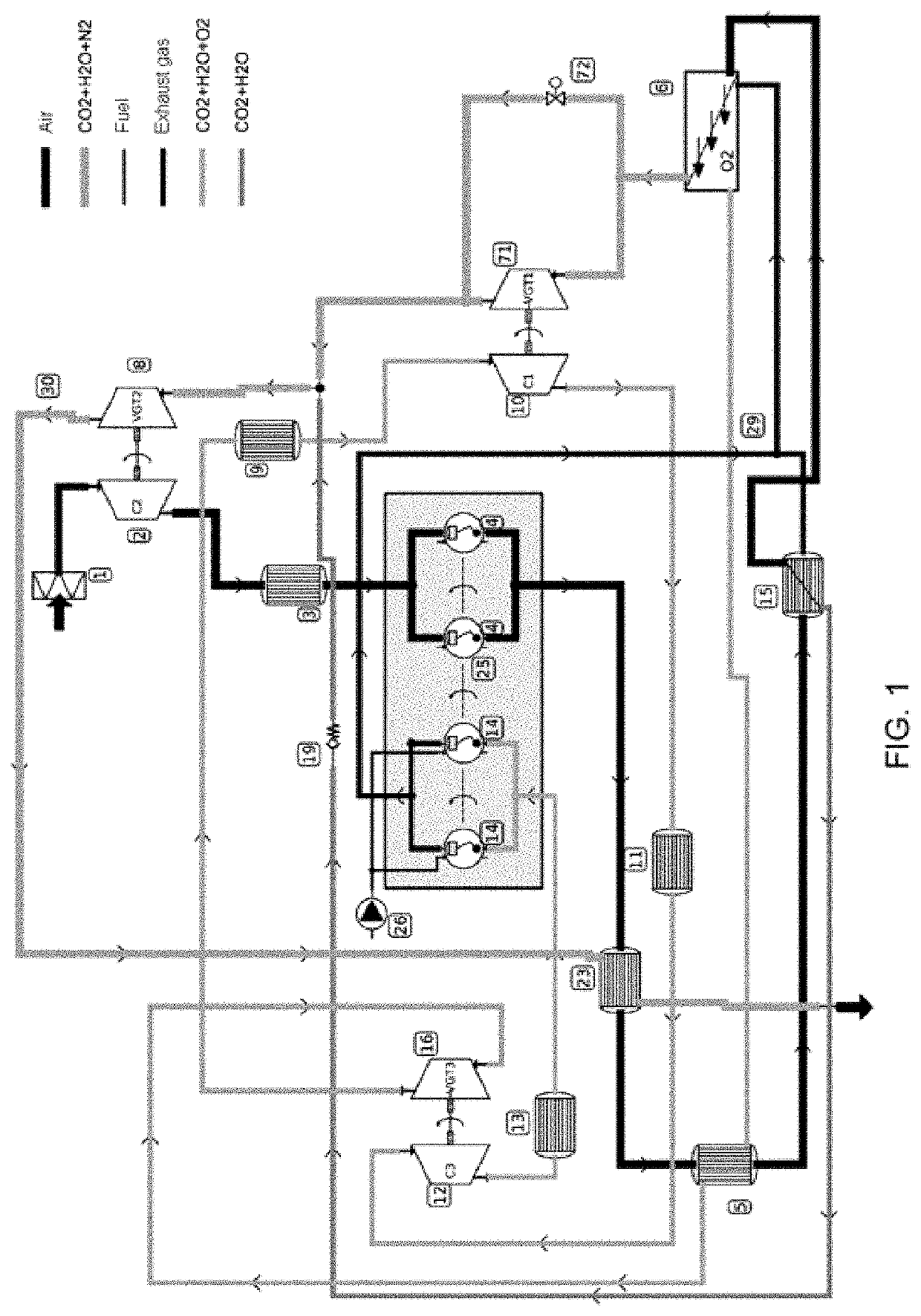
[0107]Embodiment 1 is indicated for spark ignition (SI) engines with a premixed (homogeneous) mixture without the capture of CO2. Embodiment 1 is based on a process of deflagration combustion, with subsonic speed and without self-ignition of the mixture, for the production of net mechanical power.

[0108]The degree of charge (percentage of the maximum torque) of the engine is controlled by the O2 production rate in the MIEC membrane (6). This reduces pumping losses as it eliminates the use of throttling butterfly valves to throttle airflow.

[0109]The combustion temperature is controlled by dilution of the mixture of oxidizing agent (O2) and fuel (HxCyOz) with CO2 and H2O from the actual combustion and pre-cooling. This prevents using fuel for this task (standard practice in SI engines today).

[0110]Embodiment 1 does not propose capturing the CO2 emitted by the engine. However, it does...

embodiment 2

on (SI) Engine with a Premixed Mixture Without Polluting Gas Emissions and with Capture of CO2 Produced and Removal of Atmospheric CO2

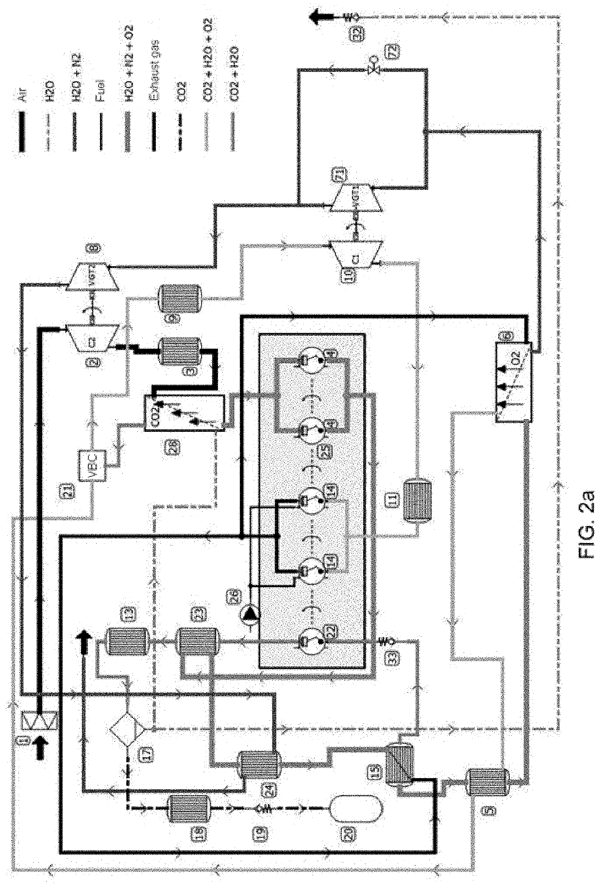
[0129]Embodiment 2 is indicated for spark ignition (SI) engines with a premixed (homogeneous) mixture with capture of atmospheric and produced CO2. Therefore, it is within the category of engines that remove CO2 from the atmosphere (emissions rate <0). Embodiment 2 is based on a process of deflagration combustion, with subsonic speed and without self-ignition of the mixture, for the production of net mechanical power.

[0130]The degree of charge (percentage of the maximum torque) of the engine is controlled by the O2 production rate in the MIEC membrane (6). This reduces pumping losses as it eliminates the use of throttling butterfly valves to throttle airflow.

[0131]The combustion temperature is controlled by dilution of the mixture of oxidizing agent (O2) and fuel (HxCyOz) with CO2 and H2O from the actual combustion and pre-cooling. This prevents usin...

embodiment 3

Ignition (CI) Engine with a Stratified Mixture and Diffusion Combustion, with an Effective Variable Compression Ratio Controlled by the O2 Production Rate; Without Polluting Gas Emissions and Without the Capture of CO2

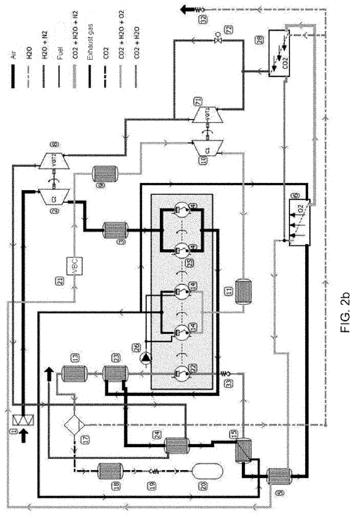
[0158]Embodiment 3 is indicated for compression ignition (CI) engines with a stratified mixture (diffusion combustion) without the emission of pollutants and without the capture of CO2. For the production of net mechanical power, embodiment 3 is based on a diffusion combustion process, with self-ignition by detonation of the premixture and combustion speed controlled by the amount of movement of fuel streams.

[0159]The degree of supercharging affects the percentage of the maximum torque in each regime through the effective compression ratio of the cycle. This effective compression ratio is variable and is controlled by the O2 production rate in the MIEC membrane. This represents a concept of size reduction, where the cylinder capacity of the engine can be reduced and t...


PUM

PropertyMeasurementUnit
temperaturesaaaaaaaaaa
pressuresaaaaaaaaaa
thicknessaaaaaaaaaa

Abstract

The invention relates to an internal combustion engine that comprises a first Brayton cycle comprising a mixed ionic-electronic conducting (MIEC) membrane that separates the O2 from the air such that the suctioned air current is free from N2; a second Brayton cycle combined in a binary manner with the first Brayton cycle and nested with a cycle selected from an Otto cycle and a diesel cycle performed by means of oxy-combustion. The second Brayton cycle transmits mechanical energy and thermal energy from exhaust gases to the first Brayton cycle. The first Brayton cycle provides to the second Brayton cycle compressed O2 from the MIEC membrane. By means of the present engine, the NOx emission into the atmosphere is prevented by the separation of N2 in the MIEC membrane.

Description

FIELD OF THE INVENTION[0001]The present invention relates to the field of the internal combustion engines, and more specifically to an internal combustion engine that burns hydrocarbons and does not emit gases that are harmful to health.BACKGROUND OF THE INVENTIONMIEC Membranes[0002]Mixed ionic-electronic conducting (MIEC) membranes are a type of dense ceramic membranes in which oxygen ions are diffused from one side to the other through the properties of the crystal structure due to a chemical potential gradient of oxygen between both sides of the membrane. The oxygen selectivity of these membranes is 100%. These membranes work at high temperatures (usually in the range of 700-1000° C.) with high air pressures (1-2 MPa) fed in on the retention side and vacuum on the permeation side, according to Air Products & Chemicals Inc., which has resulted in a major breakthrough for marketing MIEC membrane technology for pure oxygen productions.[0003]Transport of the oxygen ion is simultaneou...

Claims


Application Information

Patent Timeline
Patent Type & Authority Applications(United States)
IPC IPC(8): F02M25/12F02M37/00F02B37/04B01D53/22F02M35/10F02B29/04F02B75/10F02B33/06C01B13/02
CPCF02M25/12F02M37/0047F02B37/04B01D53/228C01B2210/0051F02B29/0406F02B75/10F02B33/06C01B13/0255F02M35/10157C01B13/0251C01B2210/0046B01D2256/12B01D2257/102B01D2257/504B01D53/229B01D2258/01F02B33/22Y02P20/151Y02T10/12F02M35/10242B01D53/22C01B13/0259Y02P20/129C01B2210/0075Y02C20/40Y02P30/00
Inventor ARNAU MARTÍNEZ, FRANCISCO JOSÉBENAJES CALVO, JESÚS VICENTECATALÁN MARTÍNEZ, DAVIDDESANTES FERNÁNDEZ, JOSÉ MARÍAGARCÍA-CUEVAS GONZÁLEZ, LUIS MIGUELSERRA ALFARO, JOSÉ MANUELSERRANO CRUZ, JOSÉ RAMÓN
Owner UNIV POLITECNICA DE VALENCIA
Learn More