Methods for eyeglass lens curing using ultraviolet light

a technology of ultraviolet light and eyeglass lens, which is applied in the field of methods and apparatus for making plastic lenses using ultraviolet light, can solve the problems of lens yellowing, lens or mold cracking, and optical distortion in the lens

Inactive Publication Date: 2000-02-08
Q2100
View PDF331 Cites 108 Cited by
  • Summary
  • Abstract
  • Description
  • Claims
  • Application Information

AI Technical Summary

Problems solved by technology

Curing of a lens by ultraviolet light tends to present certain problems that must be overcome to produce a viable lens.
Such problems include yellowing of the lens, cracking of the lens or mold, optical distortions in the lens, and premature release of the lens from the mold.
In addition, many of the useful UV-curable lens forming compositions exhibit certain characteristics which increase the difficulty of a lens curing process.
For example, due to the relatively rapid nature of ultraviolet light initiated reactions, it is a challenge to provide a composition which is UV curable to form an eyeglass lens.
Excessive exothermic heat tends to cause defects in the cured lens.
While reducing the level of photoinitiator addresses some problems, it may also cause others.
For instance, lowered levels of photoinitiator may cause the material in regions near an edge of the lens and proximate a gasket wall in a mold cavity to incompletely cure due to the presence of oxygen in these regions (oxygen is believed to inhibit curing of many lens forming compositions or materials).
Uncured lens forming composition tends to result in lenses with "wet" edges covered by sticky uncured lens forming composition.
Furthermore, uncured lens forming composition may migrate to and contaminate the optical surfaces of the lens upon demolding.
The contaminated lens is then often unusable.
During such irradiation, however, higher than desirable levels of irradiation, or longer than desirable periods of irradiation, may be required.
The additional ultraviolet irradiation may in some circumstances cause defects such as yellowing in the lens.
The low photoinitiator levels utilized in many ultraviolet curable lens forming compositions may produce a lens which, while fully-cured as measured by percentage of remaining double bonds, may not possess sufficient crosslink density on the lens surface to provide desirable dye absorption characteristics during the tinting process.
An undesirable effect of this method, however, is that the lens tends to yellow as a result of such exposure.
This method generally requires long exposure times and often the infrared radiation absorbed by the lens mold assembly will cause premature release of the lens from a mold member.
This method, however, is also associated with a higher rate of premature release.
Thicker lenses tend to be more difficult to cure with continuous non-pulsed light.
When casting a lens, particularly a positive lens that is thick in the center, cracking may be a problem.
During the process, a large temperature gradient may build up and the resulting stress may cause the lens to crack.
Once patterns leading to optical distortions form they are difficult to eliminate.
When gelation occurs there typically is a rapid temperature rise.
If the heat exchange with the surroundings is not sufficient enough there will be a runaway situation that leads to premature release, the appearance of thermally caused striations and even breakage.
Premature release of the lens from the mold will result in an incompletely cured lens and the production of lens defects.
Excess liquid that is not removed could spill over the face of the back mold member 90 and cause optical distortion in the finished lens.
High absorptivity of a photoinitiator in this range, however, is not desirable, especially when casting a thick lens.
A strongly absorbing photoinitiator will absorb most of the incident light in the first millimeter of lens thickness, causing rapid polymerization in that region.
The remaining light will produce a much lower rate of polymerization below this depth and will result in a lens that has visible distortions.
Although such lenses actually absorb very little visible light, they are cosmetically undesirable.
Photoinitiators are often very system specific so that photoinitiators that are efficient in one system may function poorly in another.
A concentration of initiator that is too high tends to lead to cracking and yellowing of the lens.
Concentrations of initiator that are too low tend to lead to incomplete polymerization and a soft material.
Sharp intensity gradients through the lens may lead to defects in the finished lens.
In addition, the yellowing tends to disappear if the lens is subjected to the above-described post-cure heat treatment.
Moreover, if not post-cured the yellowing tends to disappear at ambient temperature after approximately 2 months.
If too much TTEGDA is included in the most preferred composition, i.e. greater than about 25% by weight, however, the finished lens may be prone to cracking and may be too flexible as this material softens at temperatures above 40NC.
If TTEGDA is excluded altogether, the finished lens may to be brittle.
TMPTA also contributes to high shrinkage during polymerization.
The inclusion of too much of this material in the most preferred composition may make the finished lens too brittle.
The fully exposed region of the lens will tend to be harder, and the lens may have stresses because of this.
This effect has been observed and may cause premature release or induce cracking.
Mold defects at the edges interfere with the sealing conditions and frequently induce premature release.
It is believed that as the reaction proceeds, the heat generated tends to reduce the adhesion between the shrinking lens and the mold face.
This reduction in adhesion tends to cause the lens to pull away from the mold.
In high curvature (i.e. high power) lenses this problem tends to be even more pronounced because of two factors: (1) these lenses have more thickness and thus more material that is generating heat (which thus speeds up the reaction and generates more heat), and (2) these lenses have a greater thickness differential between the thick and thin portions of the lens, which tends to cause stress on the molds due to differential shrinkage.
It is also possible that the temperatures generated relatively deep inside a thick lens may cause some vaporization of the monomer.
Low diopter lenses may be prepared in this fashion, but higher plus or minus diopter lenses may fail.
These lower temperatures tend to permit an increase in photoinitiator concentration, which in turn may speed up the reaction and lower curing time.
Similarly, the disadvantages of a higher temperature cooling fluid may be somewhat offset by higher flowrates of cooling fluid.
The thickness of the glass molds used to cast polymerized lenses may affect the lenses produced.

Method used


Image

  • Methods for eyeglass lens curing using ultraviolet light
  • Methods for eyeglass lens curing using ultraviolet light
  • Methods for eyeglass lens curing using ultraviolet light

Examples


example # 1

OXYGEN BARRIER EXAMPLE #1

A liquid lens forming composition was initially cured as in a process and apparatus similar to that specified in Example 1. The composition was substantially the same as specified in Example 1, with the exception that hydroquinone was absent, the concentration of methylethylhydroquinone was about 25-45 ppm, the concentration of 1 hydroxycyclohexyl phenyl ketone was 0.017 percent, and the concentration of methylbenzoylformate was 0.068 percent. The composition underwent the initial 15 minute cure under the "1st UV." The apparatus was substantially the same as described for the above Example 1, with the following exceptions:

1. The air flowrate on each side of the lens mold assembly was estimated to be about 18-20 cubic feet per minute.

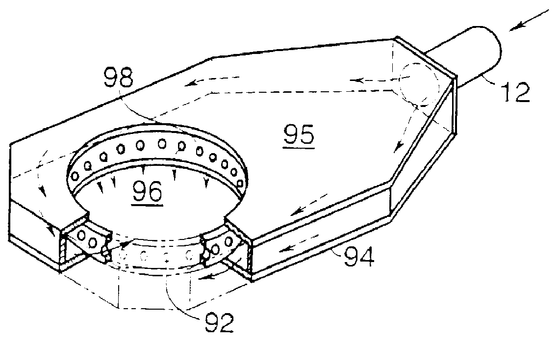
2. The apparatus was modified in that air flowed to and from the openings 96 and orifices 98 (which were themselves substantially unchanged) through a duct behind the lens forming chamber, instead of through pipes (e.g. pipe 12 i...

example # 2

OXYGEN BARRIER EXAMPLE #2

The protocol of Oxygen Barrier Example #1 was repeated except that prior to removal of the gasket the lens mold assembly was positioned so that the back face of the lens was exposed to third ultraviolet light. In this case the third ultraviolet light was at the same intensity and for the same time period as one pass of the second ultraviolet light. It has been found that applying third ultraviolet light at this point helped to cure some or all of the remaining liquid lens forming composition so that when the gasket was removed less liquid lens forming composition was present. All of the remaining steps in Oxygen Barrier Example #1 were applied, and the resultant lens was substantially dry when removed from the molds.

CONDUCTIVE HEATING

An embodiment of the invention relates to postcuring a polymerized lens contained in a mold cavity by applying conductive heat to at least one of the molds that form the mold cavity, prior to demolding the lens.

More particularly...

example 1

PULSE METHOD EXAMPLE 1

USE OF A MEDIUM PRESSURE VAPOR LAMP

An eyeglass lens was successfully cured with ultraviolet light utilizing a medium pressure mercury vapor lamp as a source of activating radiation (i.e., the UVEXS Model 912 previously described herein). The curing chamber included a six inch medium pressure vapor lamp operating at a power level of approximately 250 watts per inch and a defocused dichroic reflector that is highly UV reflective. A high percentage of infrared radiation was passed through the body of the reflector so that it would not be directed toward the material to be cured. The curing chamber further included a conveyer mechanism for transporting the sample underneath the lamp. With this curing chamber, the transport mechanism was set up so that a carriage would move the sample from the front of the chamber to the rear such that the sample would move completely through an irradiation zone under the lamp. The sample would then be transported through the zone a...


PUM

PropertyMeasurementUnit
thicknessaaaaaaaaaa
thicknessaaaaaaaaaa
wavelengthsaaaaaaaaaa

Abstract

Method and apparatus for making [and coating] a plastic lens is provided. [Oxygen barrier containing photoinitiator is used to cure incompletely cured lens portions. Radiation pulses are used to control lens curing rate. Lens is postcured while in a mold cavity using a conductive heat source.] More particularly, the invention relates to applying alternating periods of ultraviolet light to lens forming composition. Such composition is cured while controlling the rate of heat generation and/or dissipation via manipulation of the duration of the radiation or the cooling in the curing chamber. The ultraviolet light is directed toward the lens forming composition which is preferably disposed in a mold cavity formed by two mold members. The ultraviolet light may be directed in pulses or continuously.

Description

1. Field of the InventionThe present invention relates generally to methods and apparatus for making plastic lenses using ultraviolet light.2. Description of Related ArtIt is conventional in the art to produce optical lenses by thermal curing techniques from the polymer of diethylene glycol bis(allyl)-carbonate (DEG-BAC). In addition, optical lenses may also be made using ultraviolet ("UV") light curing techniques. See, for example, U.S. Pat. Nos. 4,728,469 to Lipscomb et al., 4,879,318 to Lipscomb et al., 5,364,256 to Lipscomb et al., and 5,415,816 to Buazza et al., U.S. patent application Ser. Nos. 07 / 021,913 filed Mar. 4, 1987, 07 / 425,371 filed Oct. 26, 1989, 07 / 931,946 filed Aug. 18, 1992, 08 / 123,886 filed Sep. 20, 1993, 07 / 932,812 filed Aug. 18, 1992, all of which are hereby specifically incorporated hereby by reference.Curing of a lens by ultraviolet light tends to present certain problems that must be overcome to produce a viable lens. Such problems include yellowing of the l...

Claims


Application Information

Patent Timeline
Patent Type & Authority Patents(United States)
IPC IPC(8): B29C37/00B29C35/08B29D11/00B29C35/16B29C35/00C08J7/04B29C39/02B29K105/24
CPCB29D11/00865B29C35/08B29C35/0888B29C37/0032B29D11/00442B29D11/0073B29K2105/24B29K2105/243B29C2035/0827B29C2035/1658B29C2791/001Y10S264/46Y10S425/013Y10S425/808B29D11/00009
Inventor BUAZZA, OMAR M.LUETKE, STEPHEN C.POWERS, GALEN R.
Owner Q2100
Why Eureka
Try Eureka