Hybrid propulsion system for road vehicles

a hybrid propulsion and road vehicle technology, applied in mechanical hybrid vehicles, fluid hybrid vehicles, fluid gearings, etc., can solve the problems of high noise, high fuel consumption, environmental pollution, etc., and achieve the effect of maximising the efficiency of operation of each propulsion uni

Inactive Publication Date: 2001-01-09
TRANSPORT ENERGY SYST
View PDF21 Cites 319 Cited by
  • Summary
  • Abstract
  • Description
  • Claims
  • Application Information

AI Technical Summary

Benefits of technology

It is a yet another preferred object of the invention to provide a method for controlling a hybrid prop

Problems solved by technology

The problems and drawbacks with these propulsion units include, in the case of compression ignition engines, high noise levels, environmental pollution and high fuel consumption resulting from operating at part load or idle for long periods.
This power consumption for a full sized bus results in power demands of 25 kW and 40 kW, respectively.
Braking losses are particularly significant during CBD operations, where up to four stops per kilometre are common.
There are also noise and air pollution problems attendant with the use of diesel fuel, such as the production of soot which some health authorities state is carcinogenic.
These characteristics of compression ignition engines are in sharp contrast to spark ignition engines wherein power output is controlled by throttling the engine intake fluid, thereby reducing the compression pressure (and hence the maximum combustion pressure and the efficiency of the combustion process) as well as incurring increased pumping losses.
Turning to conventional electric vehicles, a significant problem is the low energy density of standard batteries, such as the lead acid type, along with the relatively high capital cost of suitable power electronic systems for implementing regenerative operations.
Furthermore, reduced vehicle performance is experienced as the batteries approach a low state of charge.
It is extremely difficult to transfer more than 70% of vehicle kinetic energy back into a battery pack of the above mentioned mass.
When braking from higher speeds the efficiencies are worse.
Thus an electric drive is not really suited to stop-start operations.
For example an AC machine rated at 180 kW for powering an omnibus has large losses when delivering the average level road power of 40 kW.
As set out in Severinsky the cost, weight and inefficiency limit the performance of series hybrid type propulsion systems.
There is, however, no discussion of how the latter might be put into practical effect.
However, high power levels require large hydraulic machines which are conventionally clutched out of service when not needed for propulsion or retardation.
However, the oil nitrogen accumulators need to be relatively large and a pressure ratio between the maximum and minimum pressure of approx

Method used


Image

  • Hybrid propulsion system for road vehicles
  • Hybrid propulsion system for road vehicles
  • Hybrid propulsion system for road vehicles

Examples


first embodiment

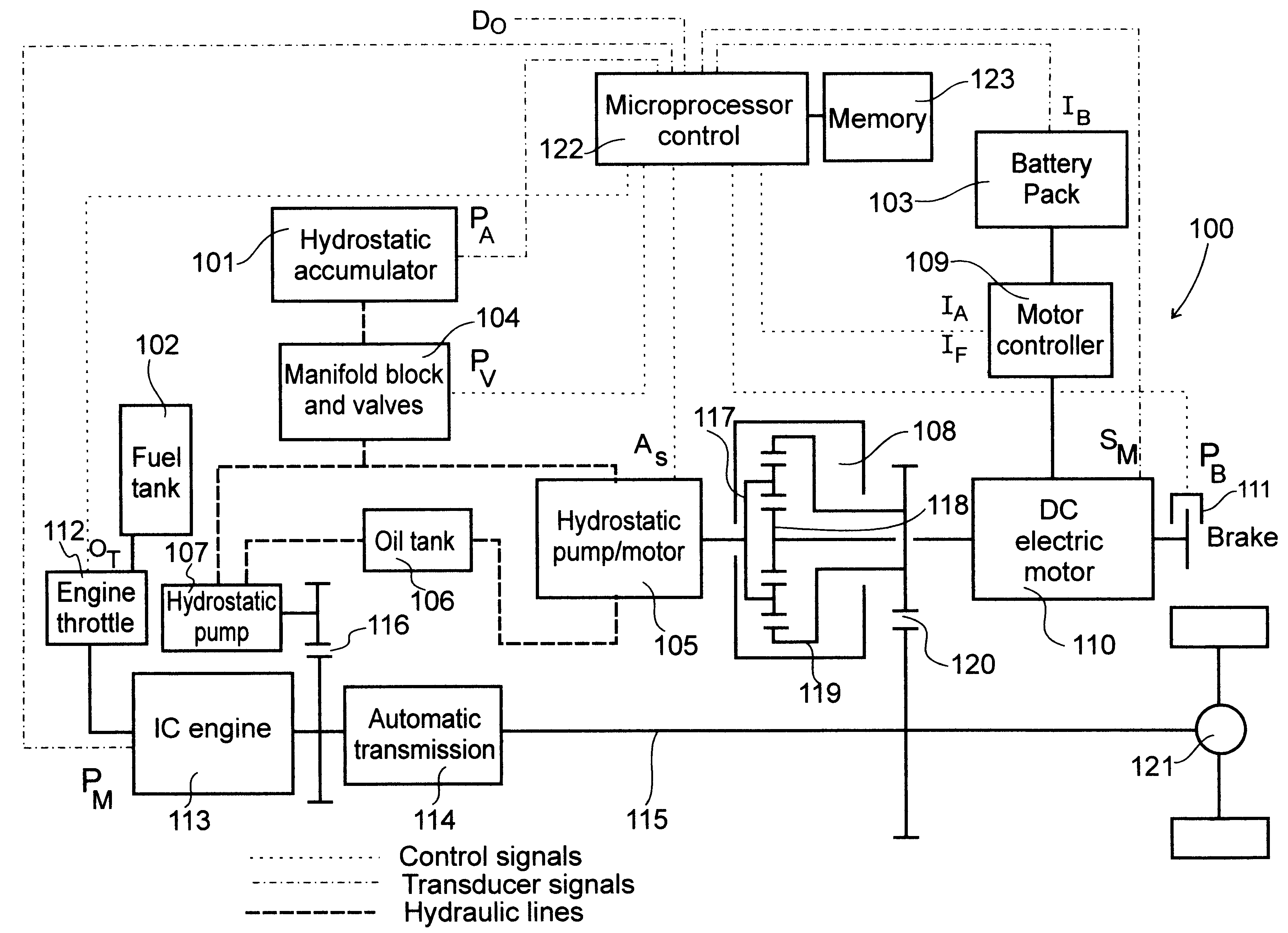
A first embodiment, which is an example of a hybrid propulsion system configured for non-transit omnibus operations in accordance with a first form of the invention, is represented by the block diagram shown in FIG. 2. The propulsion system 100 is particularly suited to relatively low range operations, due to the need to stop frequently in the case of city operations and also to the restricted hours of operation in morning and afternoon periods, in the case of school operations. The propulsion system includes three disparate energy storage means, namely a fluid pressure storage means in the form of a hydrostatic accumulator 101, a chemical energy storage means in the form of a fluid fuel tank 102, and an electrical energy storage means in the form of a battery pack 103.

The hydrostatic accumulator 101 is in a fluid hydraulic circuit with a fluid pressure control means in the form of manifold block and valves 104, a first hydraulic machine in the form of a hydrostatic pump / motor 105, ...

third embodiment

the invention, relating to another form of hybrid propulsion system configured for transit omnibus operations, is represented by the block diagram shown in FIG. 6. The propulsion system 300 is particularly suited to medium to high range operations, for example 200 to 400 km. The system may also be employed for suburban transit operations, perhaps as low as only 100 to 120 km. The propulsion system of the third embodiment again includes at least three different energy storage means.

A hydrostatic accumulator 301 is in a fluid hydraulic circuit with a fluid pressure control means in the form of manifold block and valves 305, a series of fluid pressure energy conversion means--including a first hydrostatic pump / motor 306, a second hydrostatic pump / motor 307 and a hydrostatic pump 308--and an oil tank 309. The first hydrostatic pump / motor 306 is coupled to a power splitting gearbox being a three shaft epicyclic gearbox 321, the second hydrostatic pump / motor 307 is coupled to a first gear...

fourth embodiment

FIG. 8 shows a hybrid propulsion system which shows certain modifications to the system of FIG. 6 and is particularly suited to high speed cruise operations, where it is important to substantially eliminate the losses associated with the second hydrostatic pump / motor 327. In this embodiment a modified gear set 328 is moved to the other side of the automatic transmission 314 from the IC engine 313, when compared to the first gear set 310 of the embodiment shown in FIG. 6. This is facilitated by the inclusion of a further gear for coupling the second hydrostatic pump / motor 327 and electric motor 317 to the tail shaft 315. The modified gear set 328 provides a gear ratio of 1.25:1 between the second hydrostatic machine 327 and the tail shaft 315 and, similarly, a gear ratio of 1.25:1 between the electric motor 317 and the second hydrostatic machine 327. This is a convenient arrangement when the speed changing transmission comprises an automatic gearbox and the losses associated with the...


PUM


Abstract

A hybrid propulsion system (100) for use in road vehicle operations, which propulsion system includes a power splitting mechanical transmission (108), suitably a three shaft epicyclic gearbox (117, 118, 119), for coupling to a tailshaft (115) of the vehicle; a first drive unit (105) arranged for regenerative operation and coupled to the power splitting mechanical transmission (108); a second drive unit (110) arranged for regenerative operation and coupled, independently of said first drive unit, to the power splitting mechanical transmission (108); a non-regenerative third drive unit (113) for coupling, in parallel to said power splitting mechanical transmission, to the tailshaft; and a propulsion control system (122) for coordinating operation of the drive units in accordance with a plurality of predetermined modes corresponding to a drive cycle of the vehicle. Two forms of the invention are disclosed, being suited to non-transit and transit operations, respectively. Methods for the optimal control of the hybrid propulsion system of each form of the invention are also disclosed.

Description

This invention relates to motive power systems for use in propelling vehicles. The invention particularly relates to motive power systems which include an arrangement of two or more power units coupled to a transmission, commonly termed "hybrid" propulsion systems, for road vehicles such as omnibuses.BACKGROUND TO THE INVENTIONRoad vehicles, especially omnibuses, are used for a variety of different types of operations, which may be conveniently categorised as follows:(a) central business district (CBD) or local school operations, typically travelling up to 100 km / day;(b) commercial non-transit operations, typically travelling around 120 km / day;(c) suburban transit operations, typically travelling from 100 to 200 km / day; and(d) long distance transit operations, typically travelling 400 km or more each day.Table 1 (overpage) sets out some typical operating parameters for each of these categories. The parameters include the average number of stops likely to be made by the omnibus per k...

Claims


Application Information

Patent Timeline
IPC IPC(8): B60K6/04B60K6/00B60K6/12B60K6/06B60K6/365B60K6/48B60W10/06B60W10/08B60W10/26B60W20/00
CPCB60K6/12B60K6/365B60K6/48B60W10/06B60W10/08B60W10/26B60W30/18127F16H61/4096F16H61/4148B60K6/105B60K1/02Y10T477/20B60L2270/44B60W20/00F16H47/04Y02T10/6204Y02T10/6208Y02T10/6221Y02T10/6286Y10S903/91Y10S903/96Y02T10/62B60W20/30B60W20/13
Inventor BULLOCK, KEITH JOSEPH
Owner TRANSPORT ENERGY SYST
Why Eureka
Try Eureka