Wavelength selective optical routers

a selective optical and router technology, applied in multiplex communication, transmission monitoring, instruments, etc., can solve the problems of introducing a loss of 1 db or more, affecting the power efficiency of the reflected mode, and complicated bulk optic components

Inactive Publication Date: 2001-03-13
ARROYO OPTICS
View PDF9 Cites 87 Cited by
  • Summary
  • Abstract
  • Description
  • Claims
  • Application Information

AI Technical Summary

Benefits of technology

By this arrangement, with signals propagating in opposite directions, a given wavelength in the multiple wavelength line can be dropped and a signal at the same wavelength, containing different transmission signals, can be added along the multiple wavelength transmission line. In a variant of this system, the switching sets are cross connected, such that a given wavelength is propagated through the same number of couplers regardless of the wavelengths chosen, assuring excess loss uniformity.
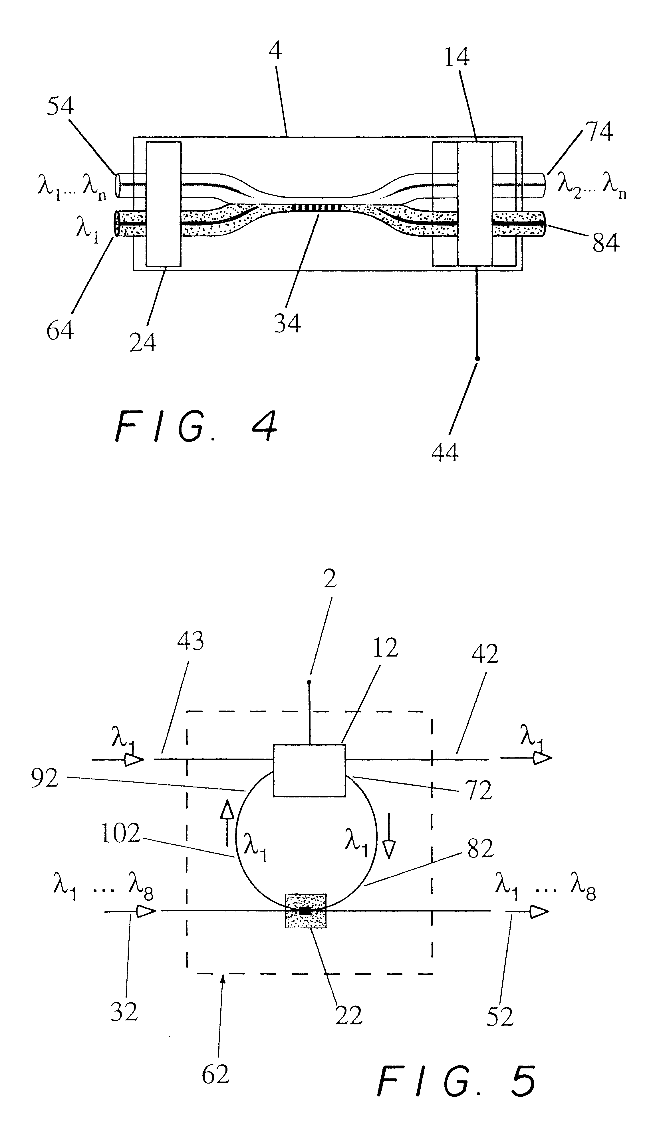
The couplers can also be configured to have a bandwidth selectivity that encompasses a number of discrete but adjacent wavelengths. Consequently, the router function can be accomplished using bundles of discrete wavelengths, rather than individual discrete wavelengths. In addition, in accordance with the invention, this function can be employed in providing a "collection box" which can be used to multiplex and / or demultiplex groups of wavelengths, thus enabling a wide wavelength band to be manipulated by establishing a hierarchy of different wavelength separations. To this end, the couplers are configured with gratings which are substantially uniformly reflected for a set of adjacent individual wavelengths. Preferably, the coupler bandwidth response includes sharp cut-off characteristics at the edges of the bandpass, such that the add / drop reflectivity response is less than -25 dB for wavelengths 1 nanometer outside the add / drop band of 2-10 nanometers. The sequentially adjacent add / drop bands thus can be separated by less than 1 nanometer. A number of such wavelength selective couplers spaced at adjacent wavelengths can demultiplex a total spectral bandwidth into individual wavelength bands densely spaced so that they are responsive over more than 75% of the total spectral bandwidth. Using such couplers, a number of adjacent discrete wavelengths in an optical transmission system can be bundled together in a multi-wavelength system. For example, a bandpass filter of 6.6 nm bandpass has less than -0.5 dB loss within the band and a 7 nm bandpass at the -25 dB level, so that a wide spectral band can be subdivided with a virtual minimum of non-usable deadband.
Couplers in accordance with the invention are written with varying amplitude characteristics in the periodic index of refraction patterns to provide both distributed wavelength response (chirping) and rapid spectral roll-off characteristics (apodization).
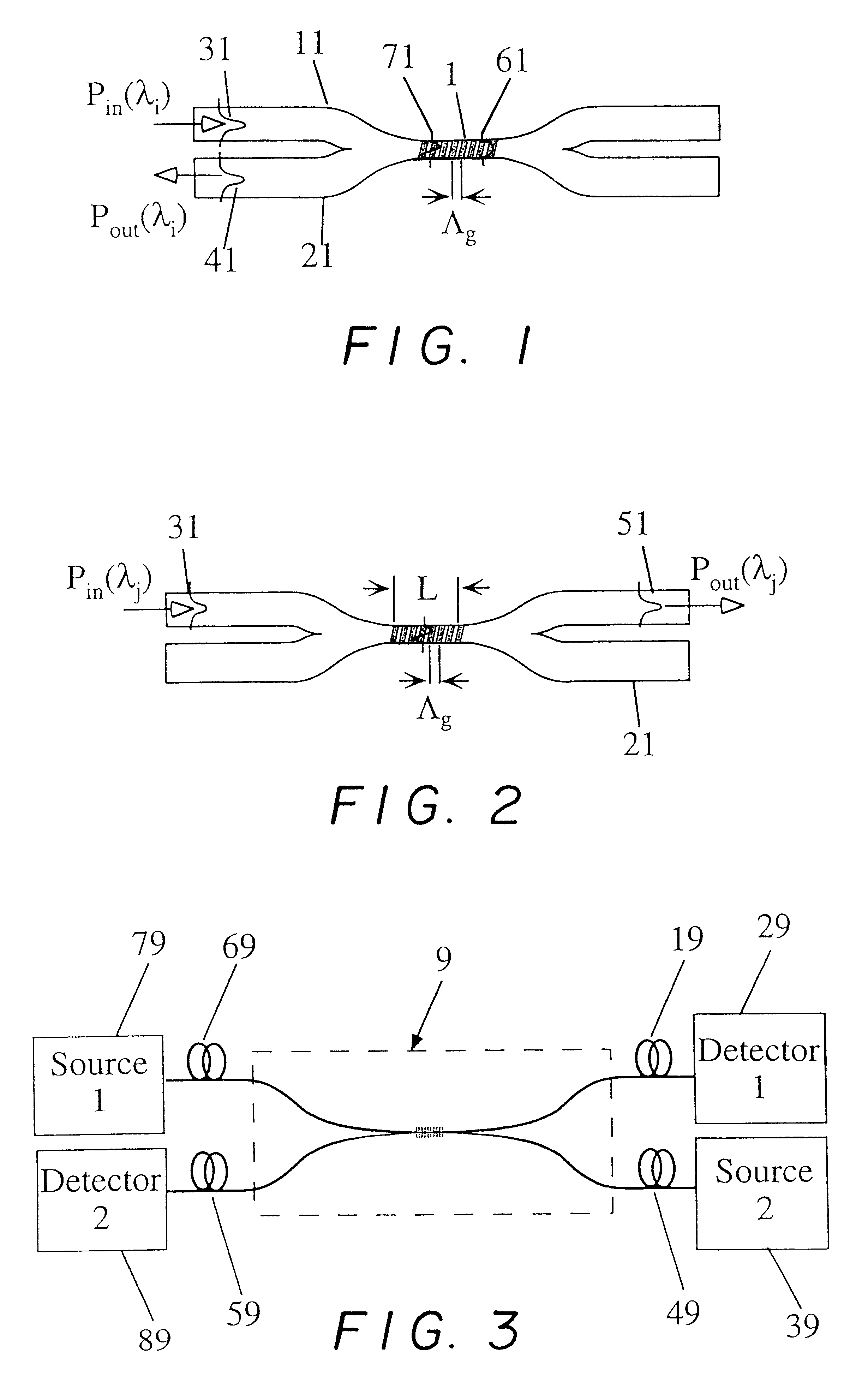
Although the grating enhanced couplers with opposite terminal pairs operate by wavelength responsive reflection, they have very low insertion loss and reflect a selected part or all of an incoming single or multi-wavelength signal to the paired terminal at one end of the waist region. Accordingly, with appropriately chosen grating characteristics, they function as a bandpass filter for an individual wavelength or a bundle of wavelengths, other incoming wavelengths being propagated through the waist region to an opposite terminal for dissipation by an optical energy absorber.

Problems solved by technology

To gain access to this reflected mode in a power efficient manner is difficult, because the wave is reflected backwards within the same fiber.
This circulator introduces an insertion loss of 1 dB or more and involves complicated bulk optic components.
This results in poor isolation of the optical signals traveling through the two waveguides, because optical power leaks from one fiber to the other.
A serious drawback of this device is that the wavelength for which light is backwards coupled into the adjacent fiber is very close to the wavelength for which light is backreflected within the original fiber (about 1 nm).
This leads to undesirable pass-band characteristics that are ill suited for add / drop filter devices designed to add or drop only one wavelength.
The separation between the backreflected and backwards coupled wavelengths is impractically small (<2 nm) for the all-fiber, grating assisted directional coupler approaches of the prior art.
The conventional grating assisted directional coupler suffers from both a relatively low coupling strength and small wavelength separation of back-reflected and backwards coupled light.
These problems arise because the two coupled optical waveguides remain physically separate and the light remains guided primarily in the original cores.
Faster electrooptic, acoustooptic or thermal switches can also be used, however, these devices usually exhibit insertion losses in excess of 3 dB.
AWG's suffer from large insertion loss, typically >6 dB per device.
Thin film interference filters offer relatively low loss ( 1 dB), but do not offer the crosstalk (30 dB) performance necessary for high channel density WDM (<200 GHz channel spacing).
A wide range of add / drop multiplexer and router technologies have been described in the prior art, but each approach suffers from relatively high insertion loss as the number of channels is scaled up.
That is, loss does not increase gracefully as the number of channels increases.
This additional loss necessitates further amplification of the optical signals passing through the router, increasing the cost and limiting their appeal in networks incorporating a high level of wavelength routing.
None of these routers and multiplexers utilize grating assisted mode couplers, and as a result do not benefit from the low loss, high rejection, low crosstalk, and bidirectionality offered by the mode coupler component.

Method used


Image

  • Wavelength selective optical routers
  • Wavelength selective optical routers
  • Wavelength selective optical routers

Examples


example 2

Wavelength Selective Optical Switch

Optical switches can be used to dynamically route information packets from one location to another or to re-configure fiber optical communications networks. These switches are typically based on electrooptic or thermooptic modulation of a directional coupler, Y-branch waveguide or Mach-Zehnder interferometer, and can achieve a modulation bandwidth in excess of 10 Ghz. They are commercially available from E-TEK, Uniphase and Akzo-Nobel, for example. An acoustic optical switch based on a fused asymmetric coupler has been described by Birks et al., Optics Letters Vol. 21, May 1996 (pp. 722-724). Relatively slow (10 ms) mechanical switches are also readily available. However, these switches typically do not allow only one of many wavelengths traveling along an individual fiber to be switched, as is desirable for wavelength routing in WDM networks. That is, these switches are not wavelength selective.

The grating assisted mode coupler enables a wavelengt...

example 3

Optical Amplifiers for WDM

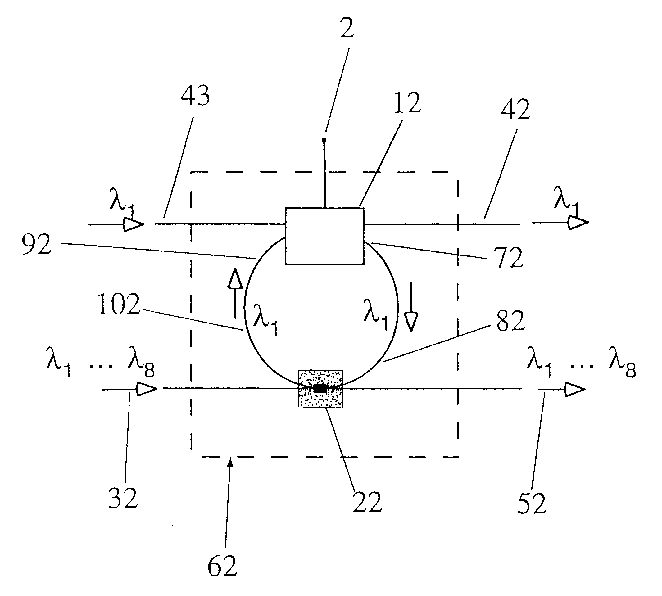
Erbium doped fiber amplifiers (EDFAs) display a sufficiently broad gain spectrum to enable multiple WDM channels to be amplified simultaneously within a single fiber. However, in some instances it is desirable to route individual wavelength channels to different locations within the optical fiber network. As a result, each wavelength travels a different distance and requires a different level of amplification. A device to amplify only a single wavelength while remaining transparent to all other wavelengths is needed. Such an amplifier 63 is fabricated by combining a grating assisted mode coupler 23 and an EDFA 13 (FIG. 6). The Erbium doped fiber can be fusion spliced between the add and drop ports of the grating assisted mode coupler, for example. In addition, a standard WDM coupler can be inserted into the add / drop loop to couple in 980 nm light from a AlGaAs pump laser, for example. The electrical input 3 adjusts the optical gain (determined by the pump l...

example 4

Wavelength Selective Optical Modulator

In another example, the active element 13 of FIG. 6 is an optical modulator. A grating assisted mode coupler 23 can be used to redirect unmodulated optical energy at a particular wavelength into a standard, wavelength insensitive optical modulator 13 and return a modulated signal at this particular wavelength back onto the original fiber with extremely low loss. The is achieved by attaching the drop and add ports of an individual, grating assisted mode coupler to the input and output ports, respectively, of a standard optical modulator. This active device 63 is transparent to all other wavelengths, eliminating the undesirable loss associated with modulating multiple wavelength channels. Optical modulators are commercially available from Uniphase Inc., for example.


PUM

PropertyMeasurementUnit
wavelengthsaaaaaaaaaa
frequency spacingaaaaaaaaaa

Abstract

Using the wavelength selectivity and low loss characteristics of optical couplers, in which index of refraction gratings in a non-evanescent waveguide merged region reflect only a selected wavelength band, signal switching and control systems of novel characteristics are provided for multi-wavelength optical communication systems. In a router, for example, selected wavelengths or wavelength bands on an add / drop line can be added to or dropped from a main fiber, by cross switching between wavelength selective loops disposed sequentially in the lines. In a collector box, as another example, selected wavelength bundles can be routed from one fiber onto multiple fibers. In a bandpass filter a selected wavelength band is transmitted with low loss while those wavelengths outside the selected wavelength band are rejected with very high loss.

Description

The present invention relates to the communication of signals via optical fibers, and particularly to systems for routing and switching optical signals based on wavelength selectivity. More particularly, the invention relates to optical devices and subsystems using wavelength selective optical couplers.DESCRIPTION OF RELATED ARTLow loss, wavelength selective couplers are important components for optical fiber communication networks based on wavelength division multiplexing (WDM). WDM enables an individual optical fiber to transmit several channels simultaneously, the channels being distinguished by their center wavelengths. An objective is to provide a precise wavelength selective coupler that is readily manufactured and possesses high efficiency and low loss.Optical fiber gratings reported in the prior art typically operate in reflection mode. To gain access to this reflected mode in a power efficient manner is difficult, because the wave is reflected backwards within the same fibe...

Claims


Application Information

Patent Timeline
Patent Type & Authority Patents(United States)
IPC IPC(8): G02B6/12G02B6/34G02F1/313G02F1/29G02B6/28H04J14/02
CPCG02B6/02114G02B6/02138G02B6/022G02B6/02204G02B6/12007G02B6/29334G02B6/29343G02B6/29383G02B6/29395G02F1/3131G02F1/3132H04J14/0206H04J14/0212H04J14/0213H04J14/0219G02B6/02085G02B6/02109G02B6/02152G02B6/2835G02F2201/307G02F2203/055H04J14/0209H04J14/021H04J14/0221
Inventor KEWITSCH, ANTHONY S.RAKULJIC, GEORGE A.YARIV, AMNON
Owner ARROYO OPTICS
Why Eureka
Try Eureka