In this method, there is a problem that the isolated Si region is determined in advance of the prepared device so that the degree of freedom of device designing is limited.
However, since the ranges of implantation energy and implantation amount for maintaining the quality of the
silicon oxide layer, the crystalline property of the surface
silicon layer and the like are so narrow that thicknesses of the surface silicon layer and the buried
silicon oxide (BOX:
buried oxide) layer were limited to particular values.
In this case, there is a problem that, since the degradation caused through these processes is superimposed on the distribution of thicknesses, the thickness uniformity deteriorates.
In the portion where the
pipe exists, the deterioration of the device characteristic results from leaks between an
active layer and a support substrate.
Further, since the amount of
ion implantation in the SIMOX is large as compared with the
ion implantation in the ordinary semiconductor process,
implantation time is lengthy even after developing the apparatus to be used exclusively for that process.
Further, in the high temperature heat treatment of the large-area
wafer, it has been pointed out that a problem of occurrence of slip due to the temperature distribution in the
wafer becomes more severe.
In SIMOX, the heat treatment is essential at high temperature, that is, 1,320.degree. C., which is not normally used in silicon semiconductor processes, so that there has been concern that this problem, including the development of the apparatus, becomes more significant.
In
polishing, uniform thickness reduction is difficult.
Particularly, in the case of thickness reduction to submicrons, the irregularity amounts to as much as tens of percents so that uniformity is a big problem.
If the size of the wafer is further enlarged, the difficulty is increased correspondingly.
Further, if the wafer is substantially increased in area, since the
plasma etching time is increased in proportion to increment of the wafer area, there is concern about extreme reduction of the
throughput.
Although the selective
etching is said to be effective for uniform thickness reduction, it has the following problems:
Since surface property after etching is bad, touch polishing is required after etching.
However, as a result, the film thickness is reduced and the thickness uniformity tends to deteriorate.
Particularly, although the amount of polishing is managed based on time, since dispersion of the polish speed is large, the control of the amount of polishing is difficult.
Thus, it becomes a problem particularly in forming an extremely thin SOI layer of, for example, 100 nm.
The crystalline property is bad because of using the
ion implantation, the epitaxial growth or the heteroepitaxial growth on the high-concentration B doped Si layer.
That is, it is difficult to improve both the ratio of etching selectively and the crystalline property or the
bonding strength.
On the other hand, in the etching of this method, since the difference in structure between porous and bulk determines the etching speed, the limitation of the heat treatment temperature is small.
On the other hand, in general, on a light transmittable substrate, typically glass, the deposited thin Si layer only becomes amorphous or polycrystalline at best, reflecting disorder in
crystal structure of the substrate, so that the high-performance device cannot be produced.
This is due to the
crystal structure of the substrate being amorphous, and thus an excellent single-crystal layer cannot be achieved even by merely depositing the Si layer.
However, the semiconductor substrate obtained through bonding normally requires two wafers one of which is removed, wastefully for the most part, through polishing, etching or the like, so that the finite resources of the earth are wasted.
Accordingly, in the conventional method, the bonded SOI has various problems of
controllability, uniformity and economics.
However, if the porosity of
porous silicon is increased, it is possible that
distortion is introduced due to the ratio of bulk silicon relative to the
lattice constant being increased so as to increase warpage of the wafer.
As a result, the following problems may be raised, that is, the number of void bonding failure regions, called voids is increased upon bonding, the crystal defect density is increased and, in the worst case, cracks are introduced into the epitaxial layer, and slip lines are introduced on the periphery of the wafer due to the influence of
thermal distortion upon the epitaxial growth.
When applying the force in the vertical or horizontal direction relative to the surface of the wafer, since the semiconductor substrate is not a fully
rigid body but an elastic body, the wafer may be subjected to elastic deformation depending on a supporting fashion of the wafer so that the force escapes and thus is not applied to the
porous layer effectively.
Further, if the
bonding strength at the
bonded interface is weaker as compared with the strength of the porous Si layer or if weak portions exist locally, the two wafers may be separated at the
bonded interface so that the initial object cannot be achieved.
Further, since, in any of the methods, the position where separation occurs in the
porous layer is not fixed, if the ratio in etching speed between the porous Si and the bulk Si is not sufficient, the
epitaxial silicon layer is first etched more or less at a portion where the
porous layer remains thin rather than at a portion where the porous layer remains thick.
Thus, the thickness uniformity of the SOI layer may deteriorate.
Particularly, when the final thickness of the SOI layer is reduced to about 100 nm, the thickness uniformity is deteriorated so that a problem may result when forming the element, such as the fully depleted
MOSFET, whose
threshold voltage is sensitive to the film thickness.
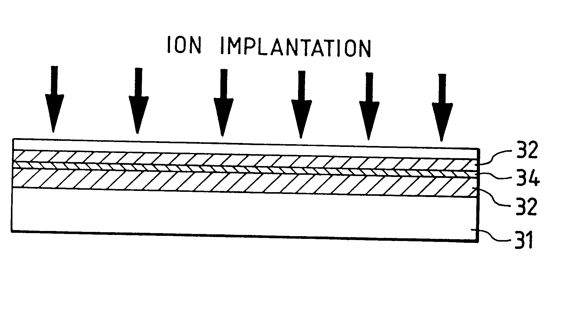
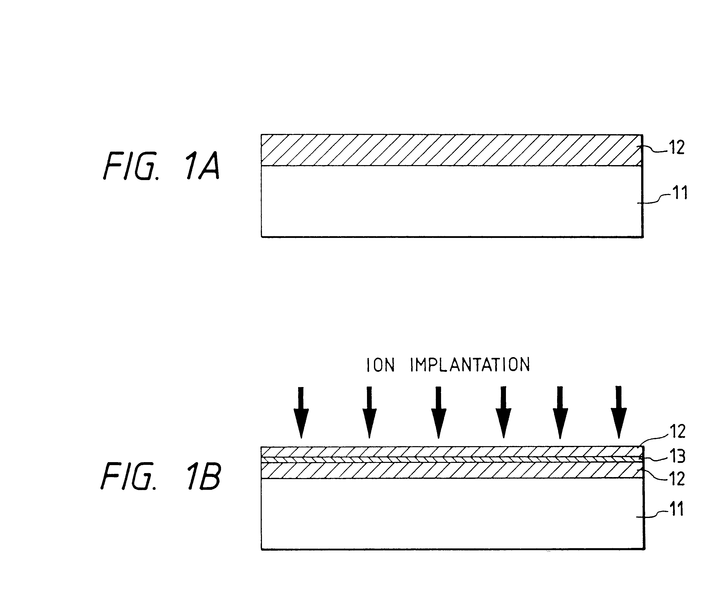
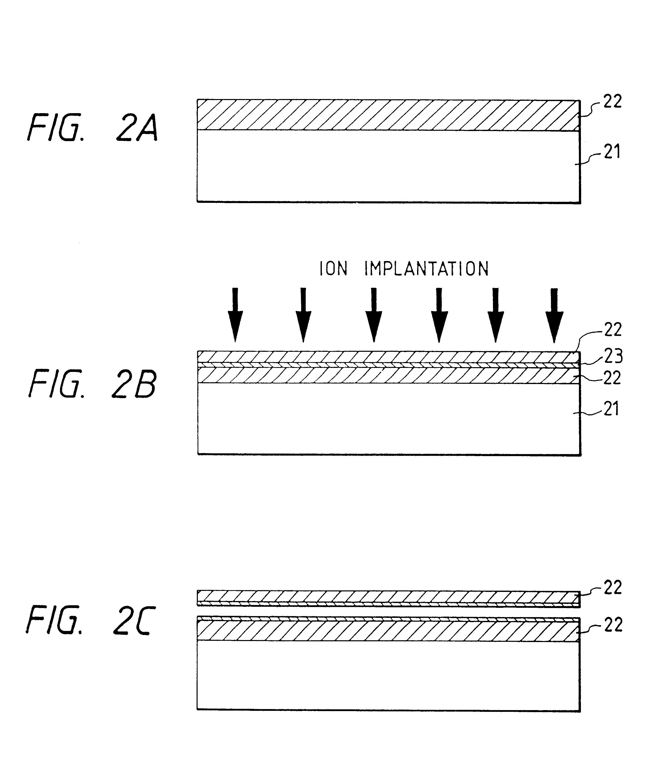
In this met hod, since
hydrogen ions are directly implanted into the single-crystal Si substrate which is then separated at the ion-implanted layer, the flatness of the SOI layer is not good.
Further, it is necessary to select an implanting condition satisfying both the
layer thickness and the separation, which creates a difficulty in control.
Further, in case of aiming at obtaining a
thin layer, the thickness of which cannot be determined by the
ion implantation, it is necessary to carry out a reducing process in thickness such as
grinding and etching, which process is nonselective, so that there is a fear of deteriorating uniformity of the thickness.
On the other hand, in general, on a light transmittable substrate, typically glass, the deposited thin Si layer only becomes amorphous or polycrystalline at best, reflecting disorderliness in
crystal structure of the substrate, so that a high-performance device cannot be produced.
This is due to the crystal structure of the substrate being amorphous, and thus an excellent single-crystal layer cannot be achieved by merely depositing the Si layer.
Specifically, in case of amorphous Si or polycrystalline Si, it is difficult, due to its defective crystal structure, to produce the drive element having the performance which is required or will be required in the future.
However, the compound semiconductor substrate is expensive and further is very difficult to increase in area.
However, due to low
thermostability and age deterioration of porous Si, its stability and reliability are poor as the substrate during or after production of the device.
However, there is a problem that the compound semiconductor substrate is expensive and low in
mechanical strength so that the large-area wafer is difficult to produce.
Further, since a
lattice constant deviation relative to bulk Si is as much as 10.sup.-3 (about 10.sup.-4 in the former case), there has been a problem that, when epitaxial-growing the single-crystal silicon layer on such
porous silicon, defects are largely introduced into the epitaxial Si layer and cracks are further introduced thereinto.
If the
surface flatness after removing the porous silicon is insufficient, the surface flattening process is performed.
Further, the Si substrate can be reused in the desired number of times until its structural strength makes it impossible.
Also in this case, the Si substrate can be reused in the desired number of times until its structural strength makes it impossible.
Thus, it is impossible to effectively use both sides of the Si substrate for bonding to the support substrate.
If the
surface flatness after removing porous silicon is insufficient, the surface flattening process is performed.
However, in their method, thicknesses of the surface silicon layer and the buried
silicon oxide layer were limited to achieve both formation of the cavity groups and relaxation of stresses introduced due to
volume expansion upon oxidation and further the formation of the grooves were necessary for selective oxidation so that the SOI structure could not be formed all over the substrate.
However, at a temperature not less than 1,000.degree. C., rearrangement of the internal holes occurs to spoil the accelerating etching characteristic.
Thus, it is impossible to effectively use both sides of the Si substrate for bonding to the support substrate.

