
Aerosol-forming porous membrane with certain pore structure

a porous membrane and pore structure technology, applied in the field of aerosol therapy, can solve the problems of difficult to reliably deliver precise doses of drugs using mdi, adverse environmental effects of propellants, inconsistent doses of patients, etc., and achieve the effect of maximizing pressure conversion and improving size distribution to the respiratory tra

Inactive Publication Date: 2003-04-08
ARADIGM
View PDF27 Cites 102 Cited by
  • Summary
  • Abstract
  • Description
  • Claims
  • Application Information

AI Technical Summary

Benefits of technology

We have now invented an extrusion nozzle that is particularly well suited to extrusion of a formulation into the entraining airstream and delivery of particles having an improved size distribution to the respiratory tract. The nozzles of the invention maximize the conversion of pressure on the formulation container to kinetic energy of the formulation being extruded, and provide aerosol particles of the desired sizes.
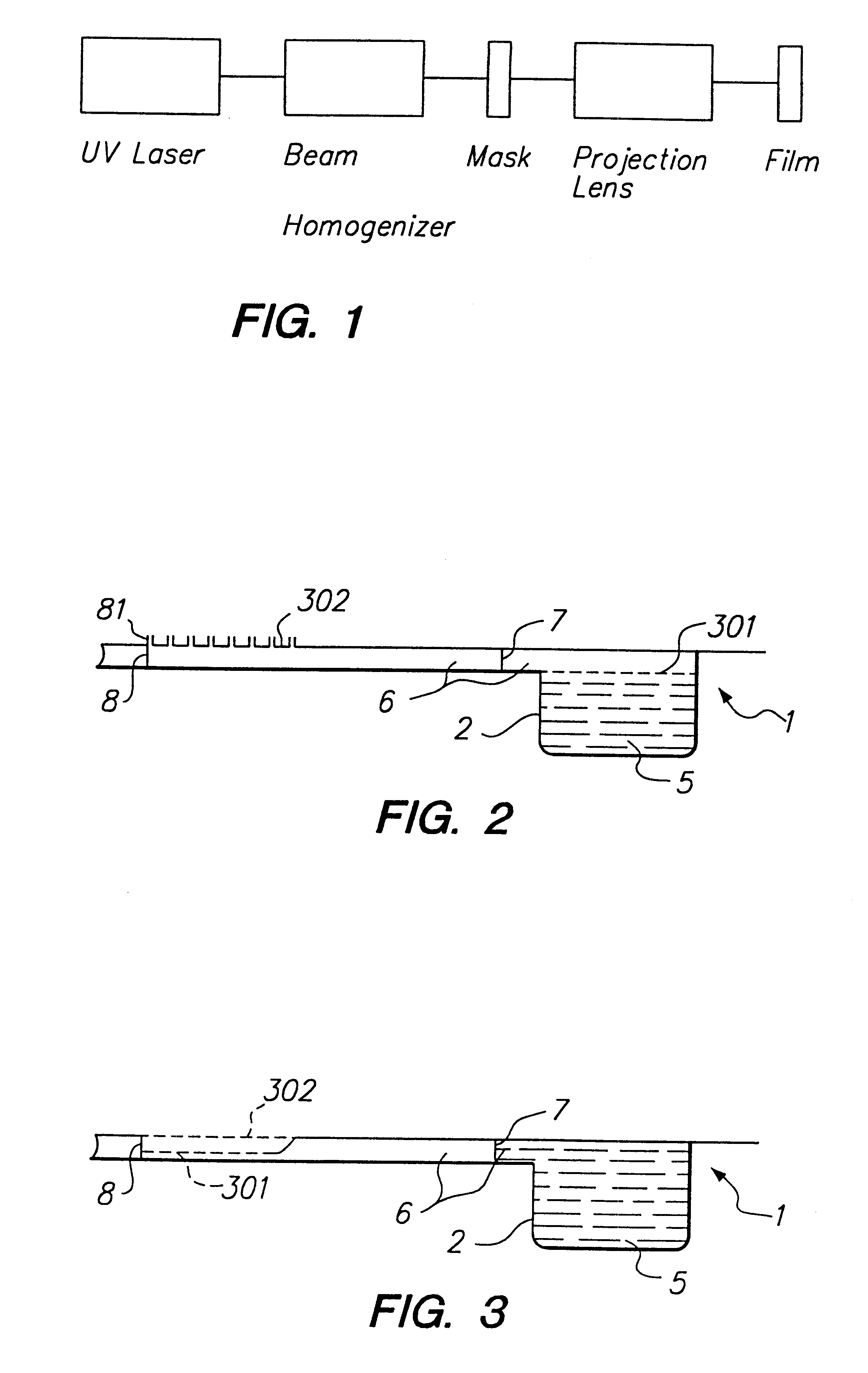
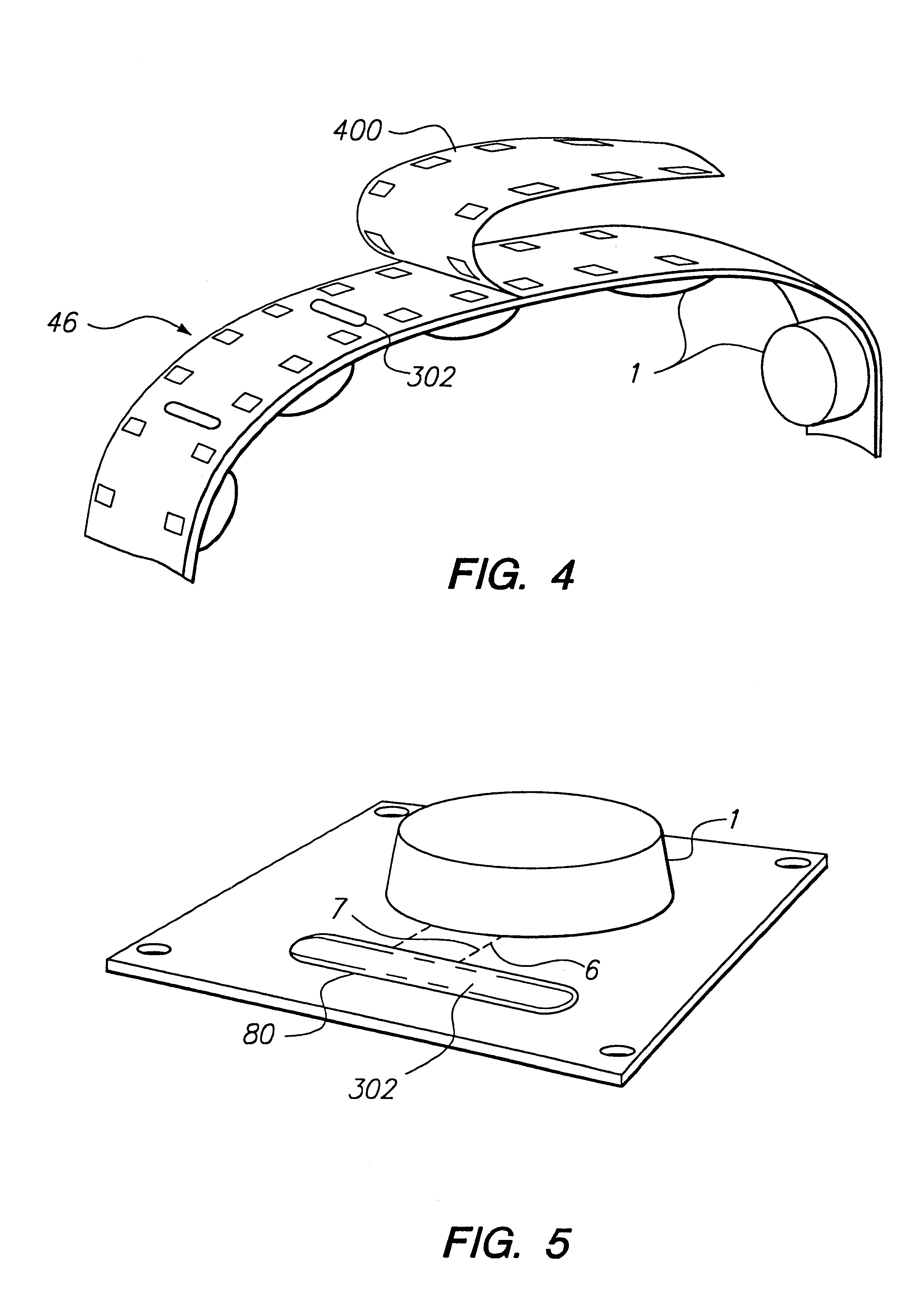
In a further aspect of the invention, a nozzle is provided wherein the area surrounding the exit aperture of the pores is elevated above the (otherwise substantially planar) exit side of the film so as to prevent intrusion of liquid into the exit aperture of the pores.
In yet another aspect of the invention, a nozzle is provided wherein the pores are incompletely formed so that, upon administration of pressure to the entrance side of the film, the exit aperture is formed by bursting outward the exit side of the pores, thereby forming an elevated area preventing liquid intrusion into the exit aperture.
Another aspect of the invention is a method for aerosolizing a formulation in a way that maximizes the amount of formulation available for inhalation, comprising extruding the formulation into an airstream through a flexible, porous membrane, where the pores are from about 0.5 to about 1.5 microns in exit aperture diameter when unflexed, and are spaced about 30-70 .mu.m apart.

Problems solved by technology

Although MDIs provide a self-contained, easily portable device, the propellants have adverse environmental effects.
In addition, it is difficult to reliably deliver a precise dosage of drug using an MDI.
The patient frequently actuates the device at the incorrect point during the breathing cycle, or breathes at the wrong flow rate while inhaling the drug.
Thus, patients may receive inconsistent doses, sometimes inspiring too little medication, other times taking a second dose after a partial failure and thereby receiving too much medication.
However, the patient's inspiratory effort may not be sufficient to satisfy the threshold to trigger drug release.
Or, although the patient's inspiration effort may be sufficient to release a metered dose, the inspired volume following the release may not be sufficient to cause the aerosol medication to pass into the desired portion of the patient's airways.
The production of an aerosol of varying particle size thus makes the delivery of a precise, reproducible dosage of medication or diagnostic agent to the desired regions of the respiratory tract extremely difficult if not impossible.
DPIs typically use bursts of air to entrain small amounts of the drug, thus forming a dust cloud of dry drug particles.
However, like MDIs, DPIs form aerosols composed of many different sizes of particles, making the delivery of a precise dose to a desired site in the respiratory tract difficult.
When precise dosing is more important, the nebulizer device and delivery methodology suffers from many of the disadvantages of metered dose inhaler devices and methodology as described above.
In addition, nebulizers generally are large and not easily transportable devices.
Yet another disadvantage of nebulizers is that they produce an aerosol which has a distribution of particle sizes, not all of which are of appropriate size to reach the targeted areas of the lung.
The use of eye drops has a number of disadvantages, primarily as a consequence of the difficulty with which drops are accepted by the patient.
The drops are relatively large, and the instinctive blink that is provoked by the arrival of a drop on the eye severely limits the amount or proportion of fluid that actually contacts the target area of the eye.
Such use of expensive treatment fluids leads to substantial uncertainty regarding the effectiveness of treatment.
Ointments are associated with similar problems in their use to accomplish ocular therapy.
However, devices that process the aerosol particle size after generation (e.g., by filtering the aerosol after it is formed from the formulation) are typically inefficient, wasteful, and / or require a substantially greater amount of force to generate the aerosol.
One impediment to aerosol formation using prior membranes is the accumulation of a liquid layer on the exit side of the membrane.
This can occur when forcible application of the formulation to the entrance side of the nozzle, rather than causing aerosolization, causes lateral spreading of liquid from the exit side, for example from poorly formed or irregular pores, or where the pressure is insufficient to consistently generate an aerosol.
This liquid layer can spread to properly functioning pores and thereby disrupt their function, further degrading performance of the nozzle.
This problem is particularly acute, for example, where the pores are closely or irregularly spaced, or where extrusion takes place over a significant period of time, or when the nozzle is to be used for repeated administration.

Method used


Image

  • Aerosol-forming porous membrane with certain pore structure
  • Aerosol-forming porous membrane with certain pore structure
  • Aerosol-forming porous membrane with certain pore structure

Examples


example 1

Preparation of Nozzles

Nozzles were prepared from thin-film polyimide (25 .mu.m, Kapton.TM. Type 100H, DuPont) using a laser (Uniphase, model s355B-100Q). The film was held by a vacuum platen to a three axis stage.

To determine the effect of power level and number of pulses on pore size, the power and pulse number was varied in a systematic fashion as pores were drilled in a single piece of Kapton. A second order polynomial fit of the pore size vs. power level was performed, and was used to estimate the power required to drill pores of diameter 1, 1.5, and 2 .mu.m. Sample nozzles were fabricated at various power levels, and pores on each sample were sized, and the average size computed. This process was iterated until a power level was determined that gave an average pore size within 5% of the desired value.

TABLE I Power Level vs Pore Size Desired Pore Size Power Level Used 1.0 .mu.m 1.1 mW 1.5 .mu.m 1.5 mW 2.0 .mu.m 1.9 mW

Nozzles for the experiments below were fabricated at these set...

example 2

Nozzles prepared as described in Example 1 were tested for generated MMAD (median size of generated aerosol), .sigma..sub.g (dispersion of the generated aerosol size distribution), and emitted dose. The nozzles were applied to AER.sub.x system disposable packages, as described in U.S. Pat. No. 5,544,646 (incorporated herein by reference), and loaded into an AER.sub.x inhaler. Nominal values for the experiment were airflow=70 liters per minute.

The MMAD of the particles prior to evaporation was measured by phase Doppler particle sizing (Aerometrics, RSA, XMT 1145, RCV 2100). Phase Doppler particle sizing uses a laser beam to scatter light from spherical aerosol particles. The scattered light is detected and analyzed to determine the particle size and velocity distribution.

The Aerometrics system was first calibrated using polystyrene latex microspheres (Duke Scientific 4205A). The particles were suspended in water, launched with a jet nebulizer (Hudson RCI, UpDraft II), and dried prior...

example 3

Purpose:

To determine the effect of variable exit hole size on the emitted dose and aerosol quality obtained with Excimer Nozzles.

The nozzle lots used in this experiment were designed to have exit hole sizes of approximately 0.8-1.5 .mu.M.

ED, MMAD, GSD and FPD results were measured.

ED--fraction of the loaded dose that is emitted from the device

MMAD--mass median aerodynamic diameter

GSD--geometric standard deviation

FPD--fine particle dose (fraction of the dose loaded in the jacket that exits the mouthpiece in particles<3.5 .mu.M aerodynamic diameter

Packet Preparation: the nozzles were drilled using a UV excimer laser. After scanning electron microscopy (SEM) to examine a portion of the nozzles, the remaining nozzle file was sealed to blister jackets. The test liquid was 45 .mu.l of cromolyn sodium (30 mg / ml) aqueous solution.

SUMMARY PERFORMANCE DATA SEM exit hole size (.mu.m) from different sub-lots ED (%) MMAD (.mu.m) GSD 1.32 .+-. 0.05 72.3 .+-. 3.9 2.51 1.48 1.45 .+-. 0.08 1.20 .+-....


PUM


Abstract

A nozzle comprised of a thin, flexible membrane material having a plurality of pores is disclosed. In one embodiment, the pores have an unflexed exit aperture diameter in the range of about 0.5 to about 2 microns (preferably about 1 micron) and are positioned substantially uniformly in the material, preferably about 50 microns apart. The nozzle preferably has a conical or trumpet-shaped cross-section. In another aspect of the invention, the exit aperture of the nozzle is surrounded by an elevated area protruding above the substantially planar exit side of the membrane in order to prevent intrusion of liquid back into the nozzle. The nozzle can be used to form an aerosol containing a pharmaceutical composition from the exit side of the nozzle upon forcible application of the composition to the entrance side of the nozzle. This aerosol can be used to administer the pharmaceutical composition, for example, to the eye or to a selected portion of the respiratory tract. The nozzle is preferably a component of a container which holds a formulation of drug.

Description

BACKGROUND OF THE INVENTIONAerosol therapy can be accomplished by aerosolization of a formulation (e.g., a drug formulation or diagnostic agent formulation) and inhalation of the aerosol. The formulation can be used to treat lung tissue locally and / or be absorbed into the circulatory system to deliver the drug systemically. Where the formulation contains a diagnostic agent, the formulation can be used for diagnosis of, for example, conditions and diseases associated with pulmonary dysfunction. In general, aerosolized particles for respiratory delivery must have a diameter of 12 microns or less. However, the preferred particle size varies with the site targeted (e.g, delivery targeted to the bronchi, bronchia, bronchioles, alveoli, or circulatory system). For example, topical lung treatment can be accomplished with particles having a diameter in the range of 0.01 to 12.0 microns. Effective systemic treatment requires particles having a smaller diameter, generally in the range of 0.5 ...

Claims


Application Information

Patent Timeline
IPC IPC(8): A61M15/00A61M11/00B05B7/04
CPCA61M15/0045A61M15/0055A61M15/0051A61M15/0043A61M11/002
Inventor GONDA, IGORSCHUSTER, JEFFREY A.PATEL, RAJESH S.
Owner ARADIGM
Learn More