
Terminal for an active labelling system

a labelling system and terminal technology, applied in the field of terminals for active labelling systems, can solve the problems of limited number of separate records, propensity of eartags to be lost, and administrative problems in the management of such records, and achieve the effect of increasing the density of information packing

Inactive Publication Date: 2003-04-29
ELECTRONICS DATA IDENTIFICATION
View PDF12 Cites 92 Cited by
  • Summary
  • Abstract
  • Description
  • Claims
  • Application Information

AI Technical Summary

Benefits of technology

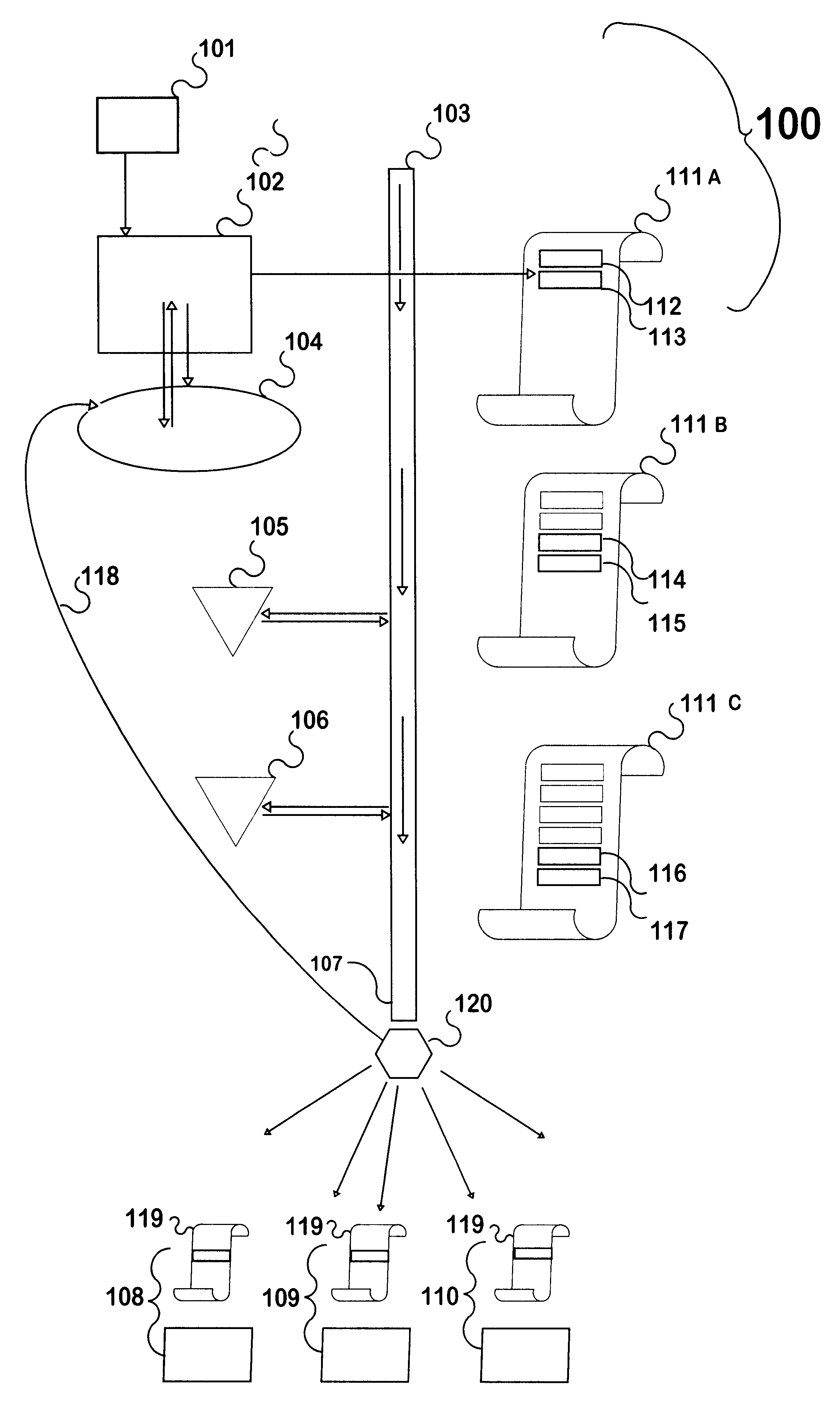
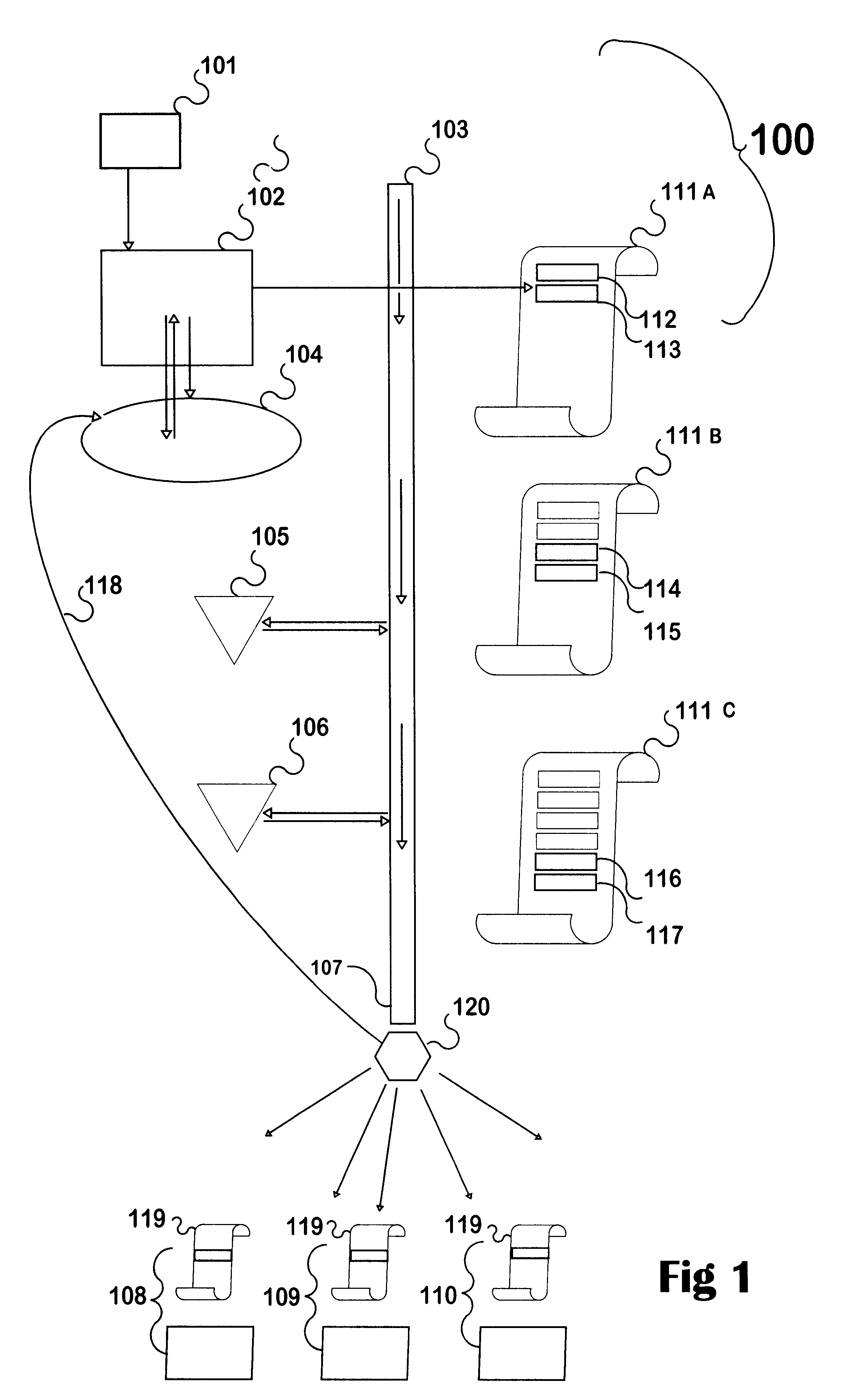
In a first broad aspect, the invention provides a terminal for an active labelling system employing wireless-powered identification tags, including: data processing means, program control means, data storage means and optionally a display and user control means; the terminal having wireless communication means capable of reading from and of writing to a wireless-powered identification tag; the tag including tag data storage means capable of storing more than one field of data within a record, wherein the terminal is capable of acquiring data comprising a code sequence from an unprotected area of data storage within a first or "key" type of wireless-powered identification tag, and if at least a part of the code sequence is recognised by the terminal as belonging to a set of predetermined security key sequences, of then adopting a security rank selected in accordance with the key sequence from a range of predetermined security ranks; the adopted security rank empowering the terminal to become capable of effective access to a predetermined set of one or more protected fields of data within a second or "tag" type of wireless-powered identification tag, so that the same terminal may serve different users at different times under different security ranks.
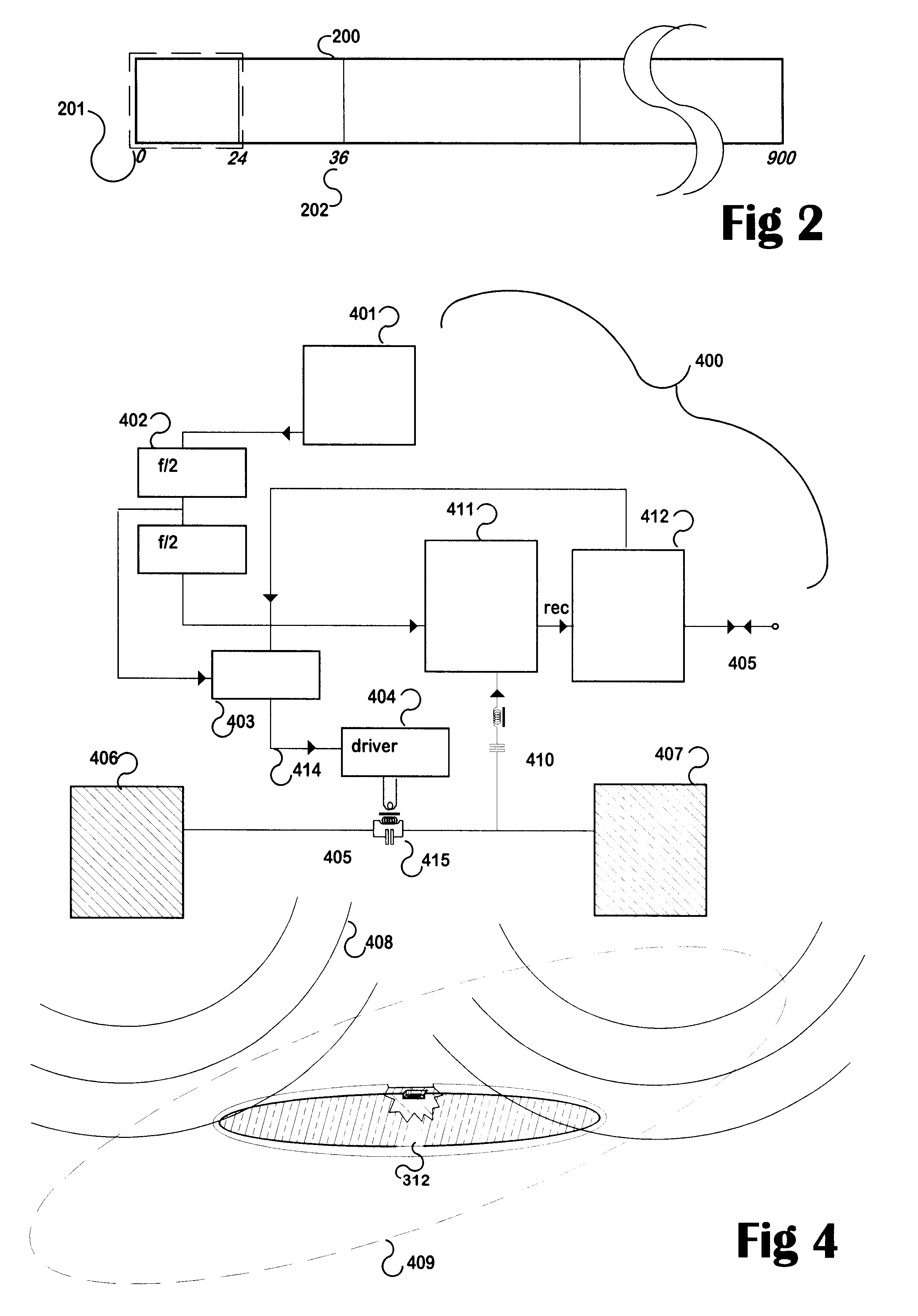
Another cheaper form of implant may comprise for example a lozenge-shaped solid object 309 perhaps made of a plastics material by means of an injection moulding technique. The lozenge has a conductive coating 313, 314 (indicated by shading) over each end, separated at the middle by a small gap 312 including a recess 311 capable of accommodating the chip 301. After the chip is glued in place preferably with a conductive glue the entire lozenge is dipped in a biologically inert insulating and protective coating 310. This article may be longer than shown in the drawing in FIG. 3, to enhance its ability to collect an alternating electrostatic field gradient

Problems solved by technology

In the case of an animal, this could be in the form of a plastic tag such as an eartag having a number of positions capable of being clipped (like a bus ticket) whenever something is to be recorded, but it is clear that disadvantages of this would include (a) the limited number of separate records, and (b) the propensity of eartags to be lost.
The management of such records provides an administrative problem, given that events impinging on an animal from time to time, or at any time, would have to be transferred accurately into a central database.
Furthermore, physically (as opposed to by-machine) reading the record as carried on the item (animal suitcase, package or the like) may require undue mental and physical agility.
None have been notably successful apart from the passive microchips widely used on pet animals.

Method used


Image

  • Terminal for an active labelling system
  • Terminal for an active labelling system
  • Terminal for an active labelling system

Examples


example 1

Transponder Example 1

An initial "proof of concept" for this invention was to employ the "Motorola" BISTATIX(R) technology. A bare silicon chip is attached to a conductive substrate that forms an electrostatically coupled aerial. This active device includes receiver means, internal power supply means, storage means, and transmitter means. A prototype aerial intended for use on packages or the like is in the shape of butterfly wings of printed, conductive ink having an overall area of 80.times.45 mm, with the chip glued in the correct orientation at a position between each of the wings--corresponding to a butterfly's body. FIG. 3 shows this at 300; with the chip 301 connected and attached across two conductive areas 302, 303 upon a substrate 304. At the time of writing, no technical information has been made available by Motorola other than the operating frequency and the existence of an approximately 900 bit memory space. The preferred transmission frequency to send information to, a...

example 2

Transponder Example 2

The currently preferred device is a Texas Instruments "Tag-it".TM. chip and assembly, manufactured together with a pickup (160 kHz) and return (80 kHz) aerial coil and encapsulated within glass. Thus the capsule is inert and easily sterilisable, preferably with a liquid disinfectant that can also be used with the injection device. The chip includes means to employ some of the received energy as internal power. The chip also includes memory; currently 1.2 Kbits which is organised to be partly "permanent" or write-once memory and partly memory capable of being written to on a number of occasions. Furthermore, software protection provides that different levels of user's priority allow access to more or less of the memory. The current memory size is rather small and encryption and compression are used, with the terminal translating between human-readable information and the stored version. Nevertheless, the stored data can include the last ten veterinary treatments....


PUM


Abstract

This invention is for a reader / writer device (terminal) for accessing item-related data in rewritable tags of the "RF-ID" type wherein each tag includes non-volatile memory. In a farm animal application each animal is implanted with an identified tag. From time to time, the terminal can be given a selected security level by reading password-like and individual identity data from a special tag held by an individual. As a result the individual can gain "read" and / or "write" to selected fields in the data record held within the tag. Further information may be added from time to time by empowered individuals. Schemes are enabled for the enhanced management of animals having such tags include accurate descriptors, proving ownership, showing compliance with disease control programmes and withholding periods after possible treatments, traceability of meat products from the shop to the farm, breeding schemes and performance recording. The use of security levels and the traceability of entries adds to the reliability of the stored information.

Description

This invention relates to provision of active labels comprising implantable or attachable identification means on items or commodities; to remote, non-contact and / or non-optical reading of and writing to the identification means itself and in particular to a terminal for interrogating transponders of an active radio-frequency identification systems for items.In many processes and systems, a group of distinct items will require to be separately identified. Examples of groups of items include the shopping in a supermarket trolley, luggage at an airport, files in an office, or animals on a farm, the initial application of this invention. Existing means for identification include simple recognition, written or printed labels, colour coding, bar coding, and the like.There is an increasing need to provide an account of the history of an item, such as a food animal, from birth right through to the point of retail sale in order to satisfy requirements such as those relating to welfare consi...

Claims


Application Information

Patent Timeline
IPC IPC(8): A01K11/00G07F7/10G07C9/00
CPCA01K11/006G06Q20/341G07F7/1008G07C9/00111G06Q20/35765G07C9/28
Inventor JOHNSON, COLIN FRANCISST GEORGE, OWEN RICHARDGREENMAN, MURRAYIRVING, GORDON DOUGLASSOMMERVILLE, CHRISTOPHER LEE
Owner ELECTRONICS DATA IDENTIFICATION
Learn More