Magnetic recording medium and magnetic recording apparatus

a recording medium and magnetic technology, applied in the field of longitudinal magnetic recording medium, can solve the problems of insufficient grain size, inability to implement amorphousness, and insufficient amorphousness, and achieve the effects of high recording density, high reliability, and improved durability and corrosion resistan

Inactive Publication Date: 2003-09-23
HITACHI GLOBAL STORAGE TECH JAPAN LTD
View PDF9 Cites 20 Cited by
  • Summary
  • Abstract
  • Description
  • Claims
  • Application Information

AI Technical Summary

Benefits of technology

Hence, the inventors have found the method of increasing the lattice constant by adding Mo or W to the Cr--Ti alloy and thereby enhancing the lattice matching with the third underlayer (Co--Ru matching layer). As a result, in actual, a lamination of the second underlayer (composed of the Cr--Ti--Mo alloy) and the third underlayer (a matching layer of the Co--Ru alloy) or a lamination of the second underlayer (composed of the Cr--Ti--W alloy) and the third underlayer (a matching layer of the Co--Ru alloy) make it possible to improve the (11.0) orientation of the magnetic layer, in particular, remarkably enhance the coercivity and the S / N ratio, enhancing a longitudinal recording density moreover.
The second underlayer may be used of an alloy having Cr as its main component and containing a 10 to 25 at. % Ti or a 2 to 20 at. % Mo or W. If the content of Ti is less than 10 at. %, the crystal matching to the third underlayer composed of a Co--Ru alloy formed thereon is made lower and the orientation of the magnetic layer is made degraded accordingly. Hence, the case is not preferable. On the other hand, if the content of Ti exceeds 25 at. %, the crystal grain size of the second underlayer is increased and thereby the medium noise is increased. Further, the content of Mo or W to be added to the second underlayer should be 2 to 20 at. %, because the content makes the crystal matching excellent. By adding an 1 to 10 at. % B to the second underlayer, preferably, the grain size of the second underlayer may be made uniform.
By forming as a protective layer carbon having an addition of nitrogen in the thickness of 3 to 6 nm and coating a lubricant layer of absorptive perfluoroalkyl polyether in the thickness of 1 to 2 nm, the resulting magnetic recording medium is made to be highly reliable and to have a high recording density. Further, the use of a carbon film with an addition of hydrogen, a film composed of a compound such as silicon carbide, or a mixed film of the compound and the carbon, makes it possible to disadvantageously improve the durability and corrosion resistance.
By mounting those media described above to the magnetic recording apparatus described with respect to the second object of the invention, it is possible to implement a highly reliable magnetic recording apparatus having a recording density of 35 megabits or more per one square millimeter.

Problems solved by technology

% or more, undesirably, it is difficult to implement the amorphousness.
%, undesirably, the amorphousness cannot be implemented.
Further, the effect caused by making the grain size smaller is not sufficient if it is less than 4 at.
Hence, the epitaxial growth of the third underlayer on the second underlayer is made difficult, so that the sufficient (11.0) orientation of the magnetic layer cannot be obtained.
However, with increase of the content of Ti, the lattice constant is made larger, while if the content of Ti exceeds 20% to 25%, the increase of the crystal grain size causes the increase of the noise on the medium.
Hence, using the underlayer composed of the Cr--Ti alloy does not realize a magnetic recording medium having 35 megabits or more per one square millimeter.
%, the amorphousness becomes difficult.
%, the crystal grain size of the second underlayer is increased and thereby the medium noise is increased.
Further, the use of a carbon film with an addition of hydrogen, a film composed of a compound such as silicon carbide, or a mixed film of the compound and the carbon, makes it possible to disadvantageously improve the durability and corrosion resistance.

Method used


Image

  • Magnetic recording medium and magnetic recording apparatus
  • Magnetic recording medium and magnetic recording apparatus
  • Magnetic recording medium and magnetic recording apparatus

Examples


first embodiment

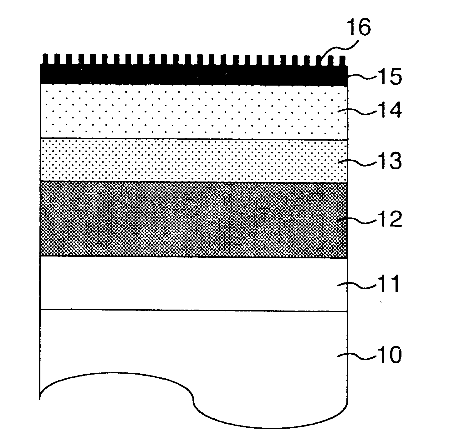
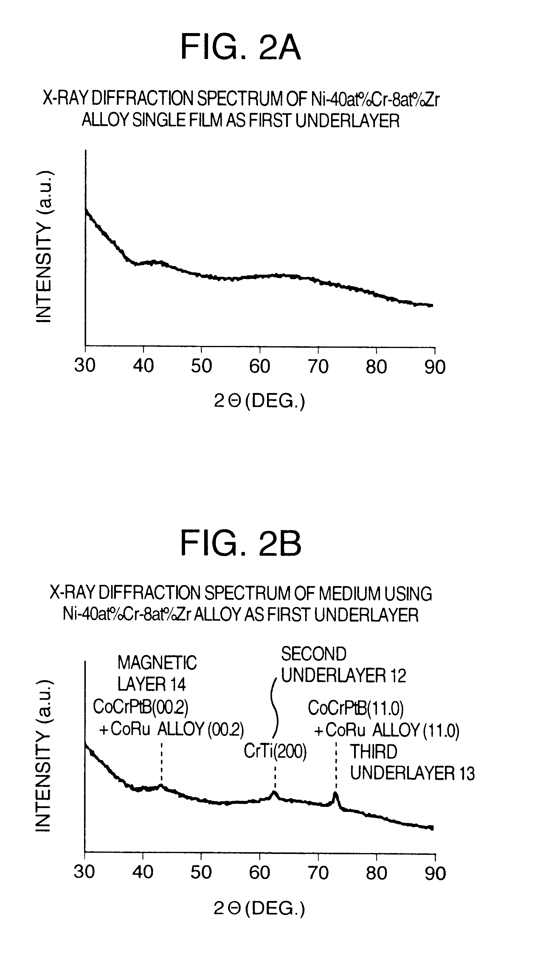
A substrate composed of alumino silicate system tempered glass being 64 mm in diameter and 0.635 mm in thickness was alkali-cleaned and then dried. Then, the substrate was put into a leaf type film forming apparatus having a plurality of chambers. Next, the apparatus was shifted into a vacuum state. A first underlayer 11 was formed in the thickness of 30 nm by the DC sputtering method in an atmosphere where an argon gas pressure is 0.8 to 1.0 Pa without heating the substrate. As the first underlayer material was used a Co-32 at. % CR-6 at. % Zr, Co-32 at. % Cr-12 at. % Hf, Co-36 at. % Cr-8 at. % Ta, Co-34 at. % Cr-25 at. % W, Co-40 at. % V-6 at. % Ti, Co-40 at. % V-8 at. % B, Co-50 at. % V-12 at. % Si, Co-45 at. % Mn-20 at. % Nb, Co-45 at. % Mn-25 at. % Mo, Ni-38 at. % Ta, Ni-55 at. % W, Ni-40 at. % Cr-8 at. % Zr, Ni-40 at. % Cr-12 at. % Ti, Ni-50 at. % V-15 at. % B, Ni-55 at. % V-15 at. % Si, or Ni-38 at. % V-30 at. % Mo alloy. After forming the first underlayer 11, the substrate w...

second embodiment

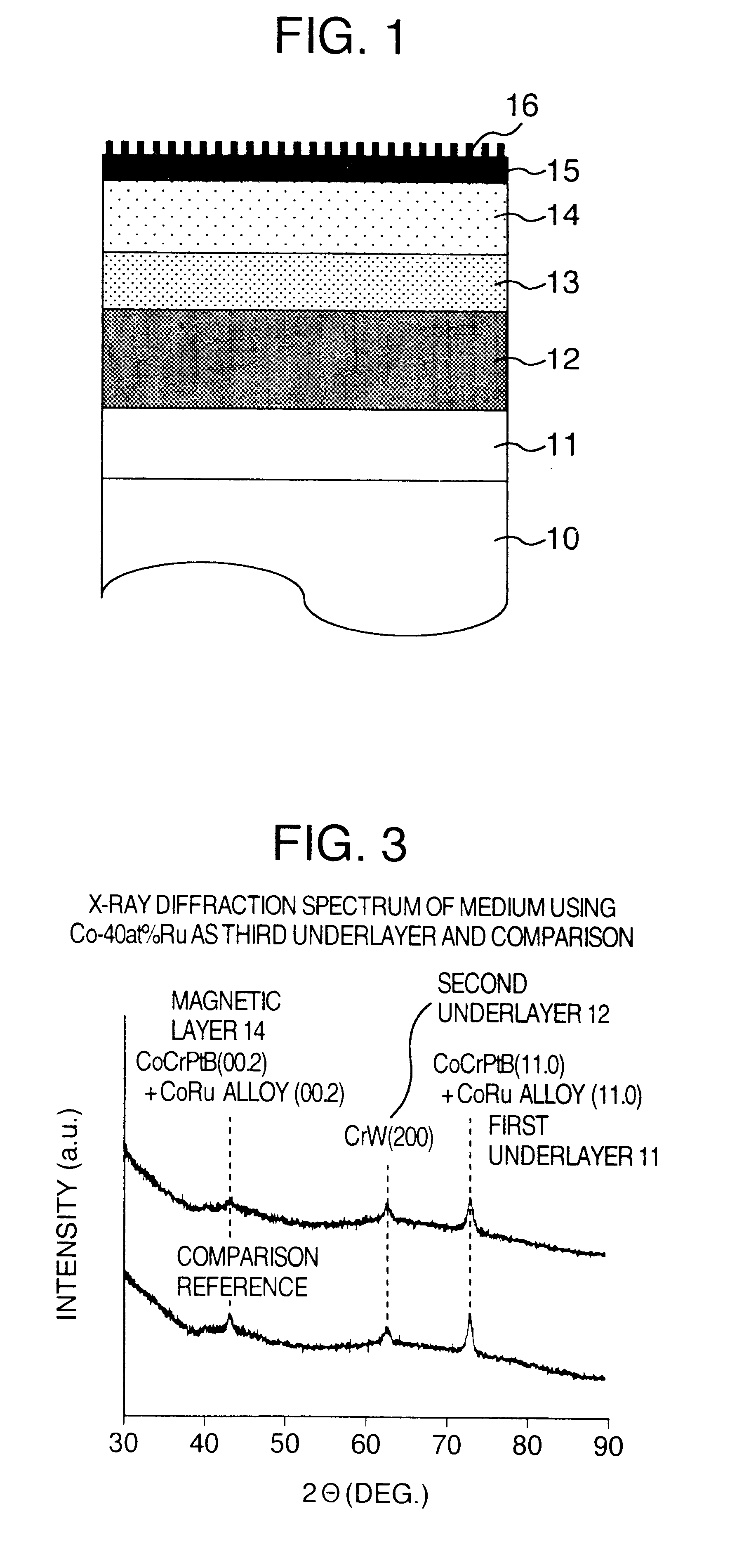
An alkali-cleaned soda lime based glass substrate 10 that is 64 mm in diameter and 0.635 in thickness was heated up to 100.degree. C. and the Co-35 at. % Cr-12 at. % Zr alloy was formed as the first underlayer 11 to have a thickness of 40 nm through the effect of the film-forming apparatus described with respect to the first embodiment. The underlayer was formed by using the mixed gas having argon as its main component with an addition of a 10% oxygen and at a gas pressure of 2.7 Pa. Afterwards, the substrate was heated up to 260.degree. C. The second underlayer 12 is formed of the Cr-25 at. % W alloy to have a thickness of 30 nm and the third underlayer 13 is formed of the Co alloy to have a thickness of 5 nm. The magnetic layer 14 is then formed of a Co-22 at. % Cr-14 at. % Pt-4 at. % B to have a thickness of 14 to 20 nm, and the carbon protective film 15 is formed with 6 nm thick. Herein, the third underlayer 13 of the Co alloy was used of the Co-30 at. % Ru, Co-35 at. % Ru, Co-4...

third embodiment

The medium having the similar composition to that of the second embodiment, in which as the third underlayer 13 is used of the Co-40 at. % Ru, Co-40 at. % Ru-1 at. % B, Co-40 at. % Ru-3 at. % B, Co-40 at. % Ru-6 at. % B, Co-40 at. % Ru-12 at. % B, or Co-40 at. %Ru-15 at. % B alloy and as the magnetic layer 14 is used of the Co-18 at. % Cr-16 at. % Pt-6 at. % B alloy in the thickness of 14 nm, was manufactured by the similar film forming process to that of the second embodiment. When this medium was subject to the X-ray diffraction measurement, like the embodiment of the second embodiment, what was observed is only the (200) diffraction peak of the CrW underlayer 12 and the (11.0) diffraction peak of a mixture of the Co alloy underlayer 11 and the CoCrPtB magnetic layer 14.

The magnetic layer included in this embodiment was observed by using the high resolution transmission electron microscope. The lattice image was magnified to 2 million times and imaged. The grain sizes of about 200...


PUM

PropertyMeasurementUnit
grain sizeaaaaaaaaaa
crystal grain sizeaaaaaaaaaa

Abstract

The longitudinal magnetic recording medium includes a non-magnetic substrate, a first underlayer having at least one of an amorphous structure and a fine crystal structure formed on the non-magnetic substrate, a second underlayer having a body-centered cubic structure formed on the first underlayer, a third underlayer having a hexagonal closed packed structure formed on the second underlayer, and a magnetic layer having the hexagonal closed packed structure formed on the third underlayer, wherein the third underlayer is composed of an alloy containing Co and Ru.

Description

1. Field of the InventionThe present invention relates to a longitudinal magnetic recording medium with noise suppressed and stability improved, and more particularly to a magnetic recording apparatus having a high recording density which is arranged to use the longitudinal magnetic recording medium.2. Description of the Related ArtIn recent days, a request has been increasingly elevated for enlarging a volume of a magnetic disk drive. Accordingly, the magnetic head has been requested to have a far higher efficiency and the recording medium has been requested to have a far higher coercivity and lower noise.The magnetic head is used of a composite head that includes both an inductive head for recording data and a spin-valve type head for reading back data. The spin-valve type head is a read-back head that is composed of a magnetoresistive sensor having a plurality of conductive magnetic layers whose directions of magnetization are relatively changed by the outside magnetic field so t...

Claims


Application Information

Patent Timeline
Patent Type & Authority Patents(United States)
IPC IPC(8): G11B5/73G11B5/62G11B5/64G11B5/00
CPCG11B5/656G11B5/7325G11B5/00Y10T428/12854Y10T428/12465Y10T428/12944Y10S428/90G11B5/737
Inventor KANBE, TETSUYAYAHISA, YOTSUOMATSUDA, YOSHIBUMIINAGAKI, JOSAKAMOTO, KOJI
Owner HITACHI GLOBAL STORAGE TECH JAPAN LTD
Why Eureka
Try Eureka