Non-volatile electrically alterable semiconductor memory device

a semiconductor memory and non-volatile technology, applied in read-only memories, static storage, instruments, etc., can solve the problems of reducing the efficiency of hot electron injection in the channel, corresponding programming speed, and practically impossible to further scale the cell itself, etc., to achieve fast programming capabilities, high density memory, and low voltage

Inactive Publication Date: 2003-11-25
INTERUNIVERSITAIR MICRO ELECTRONICS CENT (IMEC VZW)
View PDF16 Cites 22 Cited by
  • Summary
  • Abstract
  • Description
  • Claims
  • Application Information

AI Technical Summary

Benefits of technology

An aim of the invention is to develop a high density memory device having fast programming capabilities, using low voltages, being scalable and being easy to process.

Problems solved by technology

This supply voltage scaling is known to degrade the Channel Hot Electron Injection efficiency and, hence, the corresponding programming speed considerably.
The problem with this solution is two-fold: (1) since the internally generated programming voltages are not scaled down with respect to the technology generation, it becomes practically impossible to further scale the cell itself, in terms of both vertical (dielectric thicknesses) and lateral (gate length) dimensions; (2) due to the high power needed to trigger the Channel Hot Electron Injection, it becomes harder and harder to supply these voltages on-chip from a high voltage generator or charge pumping circuit.
However, a further improvement is limited by tunnel-oxide scaling limits and by the very high voltages (.about.15V) needed on chip for Fowler-Nordheim Tunnelling, both compromising device reliability and process scalability.
However, there are some drawbacks in the HIMOS.RTM. cell concept.
First, there is a drawback of the additional program gate, which increases the cell area considerably in the case of a double polysilicon technology.
Another drawback is related to the decoder design.
This in turn requires a small charge pump in the row decoder, which has a small but negative impact on the access time and power consumption.
Further, there is a reliability problem associated with the program gate's disturb phenomenon.
Further, another problem is due to the appearance of Stress-Induced Leakage Current ("SILC").
When the cell has been written and erased for a large number of times, the tunnel oxide quality is deteriorated in such a way that the application of a small read-out voltage at the drain can cause slow discharging of programmed cells.
There are main disadvantages associated with these sidewall-gate devices.
However, it is very difficult to control this selective etching operation.
Therefore, this technique is not to be considered as a standard process step for CMOS.
Therefore, the injection efficiency is compromized by isolation requirements.
Also, since the part of the transistor channel which is controlled by the sidewall gate is much shorter than the part controlled by the floating gate, a larger portion of the external drain voltage will be lost for the channel hot-electron generation at the injection point.
However, the main problem with these devices is the difficulty for contacting the cells in a large array of memory cells.
However, some drawbacks of the sidewall-gate device are still present in this memory cell.
As already mentioned above, the thickness of the polysilicon that determines the width of the spacer is usually smaller than the minimum feature size, which compromises the hard-off situation that is highly desired in a memory array.
This makes the leakage problem during read-out even more critical.
This will further decrease the coupling ratio between the control gate and the floating gate, since the oxide between the sidewall and the select gate has to scale because of its impact on the source-side injection efficiency (see above).
However, this solution compromises the major advantage of this cell, which is its high integration density.
Additionally, the erase voltage is still very high (-11V according to the application), which makes the concept unsuited for embedded memory applications where these high negative voltages would introduce too high an additional processing cost.
The major difference with the previously discussed prior art is the absence of a sidewall gate.
First of all, it is well-known that such a processing scheme introduces considerable complexity which makes it impossible to use in an embedded memory application.
This restriction compromises scaling in general and, more in particularly, decreases the injection efficiency which is directly linked to the thickness of this spacing as explained extensively by J. Van Houdt et al. in IEEE Transactions on Electron Devices, vol.39, no.5, May 1992.
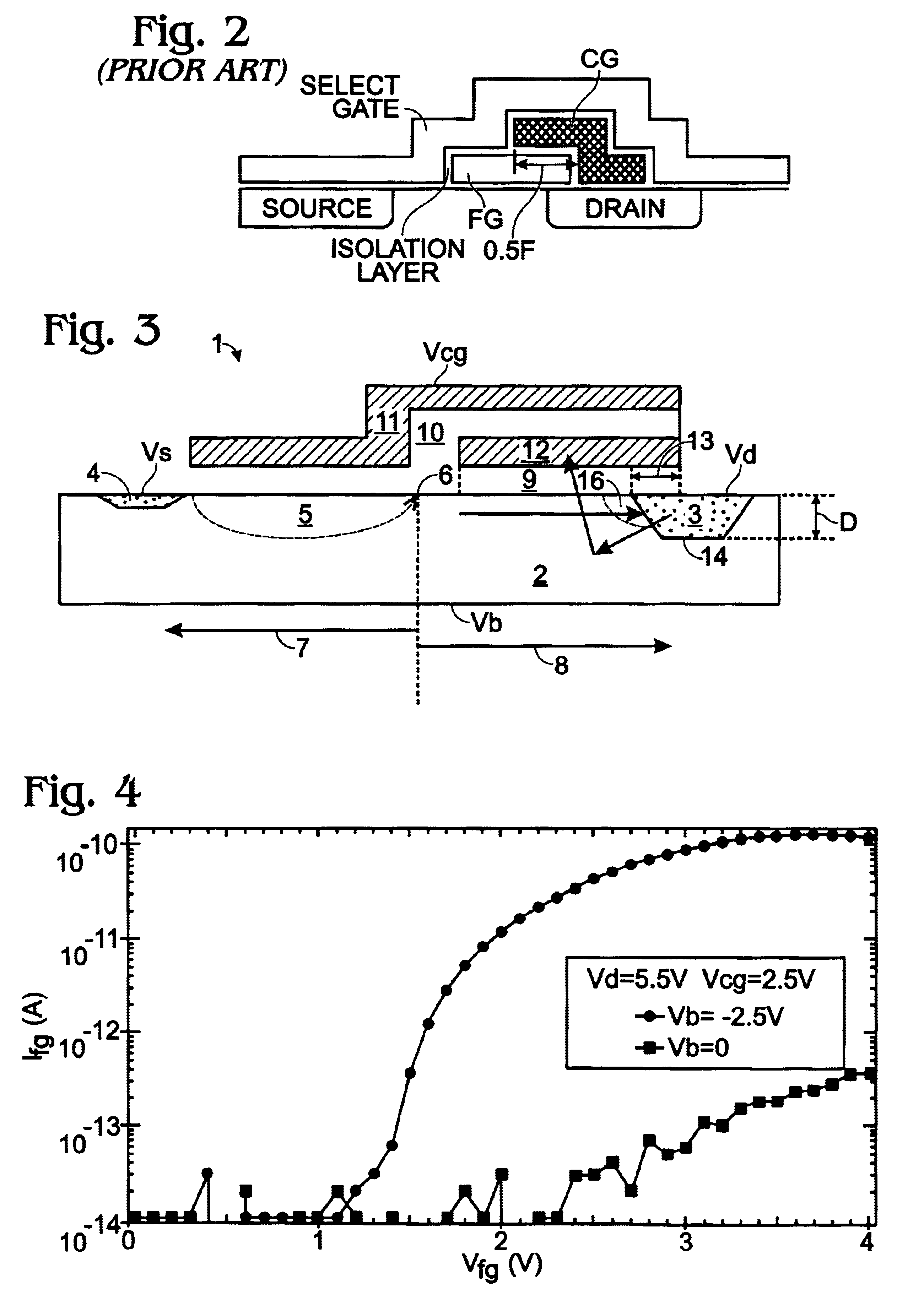
The second embodiment (FIG. 4 in that patent and FIG. 2 in the present application) still suffers from problems.
Obviously, this layer can not be made very thin and, hence, the injection efficiency will be compromised since the same layer is also serving as the spacing oxide between select gate and floating gate (see FIG. 2).
A second problem with the Fukumoto cell is the following: the second polysilicon (control) gate should cover most of the floating gate in order to increase the coupling ratio and hence reduce the programming voltage.
Although the above-mentioned application Ser. No. PCT / BE98 / 00134, WO 99 / 13513 solves the above-mentioned problems, it still requires 3 polysilicon layers which is much more complicated for the processing of the chip than a double polysilicon scheme.
al. These references all suffer from a variety of problems such as a high processing complexity and / or the need for high erase volta
Yeh et al. show a split gate cell with a very complicated interpoly formation scheme which, again, makes this concept unsuited for embedded memory.
The memory cell described in U.S. Pat. No. 5,572,054 however has the disadvantage that high voltages are needed for both programming and erasing the memory cell.
This can lead to an increase in the size of the memory device.

Method used


Image

  • Non-volatile electrically alterable semiconductor memory device
  • Non-volatile electrically alterable semiconductor memory device
  • Non-volatile electrically alterable semiconductor memory device

Examples


Embodiment Construction

Referring to the drawings, FIG. 3 is a block diagram illustrating a device arranged to employ exemplary embodiments of the present invention. As shown in FIG. 3, the device comprises a transistor 1 having a substrate 2 provided with a drain 3, a source 4, and a channel region 5 extending between the source 4 and the drain 3. The substrate 2 has a split point 6 between the source 4 and the drain 3. The split point 6 forms a separation between a first region 7 extending from the split point 6 in a first direction towards the source 4 and a second region 8 extending from the split point 6 in a second direction towards the drain 3. A first insulating layer 9 is applied on the substrate 2 and extends in the second region 8 over at least a portion of the drain 3 and at least a portion of the channel region 5. A second insulating layer 10 is applied on the substrate 2 in the first region 7, where it separates the substrate 2 from a control gate 11. The second insulating layer 10 extends fu...


PUM


Abstract

Apparatus for an electrically programmable and erasable memory device and methods for programming, erasing and reading the device. The device has a single transistor including a source, a drain, a control gate and a floating gate positioned between the control gate, the source and the drain, where the floating gate is capacitively coupled to the drain. At least one part of the floating gate is partly positioned between the control gate, the drain and the source, and the other part of the floating gate overlaps with the drain. Further, the single transistor of the device includes means for injecting hot electrons generated by the drain induced secondary impact ionization onto the floating gate. Additionally, the means are arranged to induce Fowler-Nordheim tunnelling of charges from the floating gate to the drain.

Description

The present invention relates to fast programmable Electrically Erasable Programmable Read-Only Memory devices and method for operating such devices.Nowadays, most Flash memories use Channel Hot Electron Injection ("CHEI") at the drain side of the memory cell, or Fowler-Nordheim Tunnelling ("FNT") for programming. The Channel Hot Electron Injection mechanism provides a relatively high programming speed (.about.10 .mu.s) at the expense of a high power consumption (.about.400 .mu.A / bit) which limits the number of cells that can be programmed simultaneously (so-called page-mode programming) to a maximum of 8 bytes (Y. Miyawaki et al., IEEE J. Solid-State Circuits, vol.27, p.583, 1992). Furthermore, in order to allow a further scaling of the transistor dimensions towards 0.18 .mu.m and below, supply voltage scaling from 3.3V towards 1.8V also becomes mandatory. This supply voltage scaling is known to degrade the Channel Hot Electron Injection efficiency and, hence, the corresponding pro...

Claims


Application Information

Patent Timeline
Patent Type & Authority Patents(United States)
IPC IPC(8): G11C16/04H01L21/28H01L21/336H01L21/02H01L29/66H01L29/40H01L29/423H01L29/788
CPCG11C16/0425H01L21/28273H01L29/7886H01L29/66825H01L29/42324H01L29/40114
Inventor HOUDT, JAN VANXUE, GANG
Owner INTERUNIVERSITAIR MICRO ELECTRONICS CENT (IMEC VZW)
Why Eureka
Try Eureka