Electrolytic cell for hydrogen peroxide production and process for producing hydrogen peroxide

a technology of hydrogen peroxide and electrolysis cell, which is applied in the direction of electrolysis components, chemistry apparatus and processes, water/sludge/sewage treatment, etc., can solve the problems of untreated hypochlorous acid, adversely affecting the ecosystem, and affecting environmental conservation

Inactive Publication Date: 2004-07-27
DE NORA PERMELEC LTD
View PDF3 Cites 268 Cited by
  • Summary
  • Abstract
  • Description
  • Claims
  • Application Information

AI Technical Summary

Problems solved by technology

The incineration of wastes can generate carcinogenic substances (dioxins) in the emission gas depending on combustion conditions and thereby adversely affect the ecosystem.
The safety of waste incineration is hence regarded as questionable.
However, the discharge of untreated hypochlorous acid poses problems concerning environmental conservation because not only hypochlorous acid itself but also the organochlorine compounds and chlorine gas which generate upon decomposition of the acid are harmful.
Consequently, use of hypochlorous acid is being increasingly restricted.
However, hydrogen peroxide is unstable and incapable of long-term storage.
However, these techniques are impractical because the current efficiency is low.
Although a technique in which a similar method is conducted at high pressure to thereby heighten efficiency has been proposed, this technique is also impractical from the standpoint of stability.
However, this method is only useful in limited applications because the hydrogen peroxide concentration obtained is low and the method is costly.
In the treatment of tap water, well water, seawater, or other water containing multivalent metal ions in a large amount, there are cases where a hydroxide deposits on the cathode surface to give rise to problems such as, e.g., the inhibition of power feeding.
When feed water having a low electrolyte concentration as in soft water is used for electrolytically producing hydrogen peroxide, the current density is low and this method is hence unsuitable for the production of a large amount of hydrogen peroxide.
In addition, an increased load is imposed on the electrodes, resulting in a shortened electrode life.

Method used


Image

  • Electrolytic cell for hydrogen peroxide production and process for producing hydrogen peroxide
  • Electrolytic cell for hydrogen peroxide production and process for producing hydrogen peroxide

Examples


example 1

An iridium oxide catalyst was deposited onto a porous titanium plate by a pyrolytic method in an amount of 10 g / m.sup.2 to obtain an anode.

A graphite powder (TGP-2, manufactured by Tokai Carbon Co., Ltd.) was kneaded together with a PTFE resin. The resultant mixture was formed into a sheet and burned at 330.degree. C. to obtain a 0.5 mm-thick sheet. This sheet as an oxygen gas diffusion cathode was united with a cathode feeder consisting of a porous graphite plate having a thickness of 5 mm.

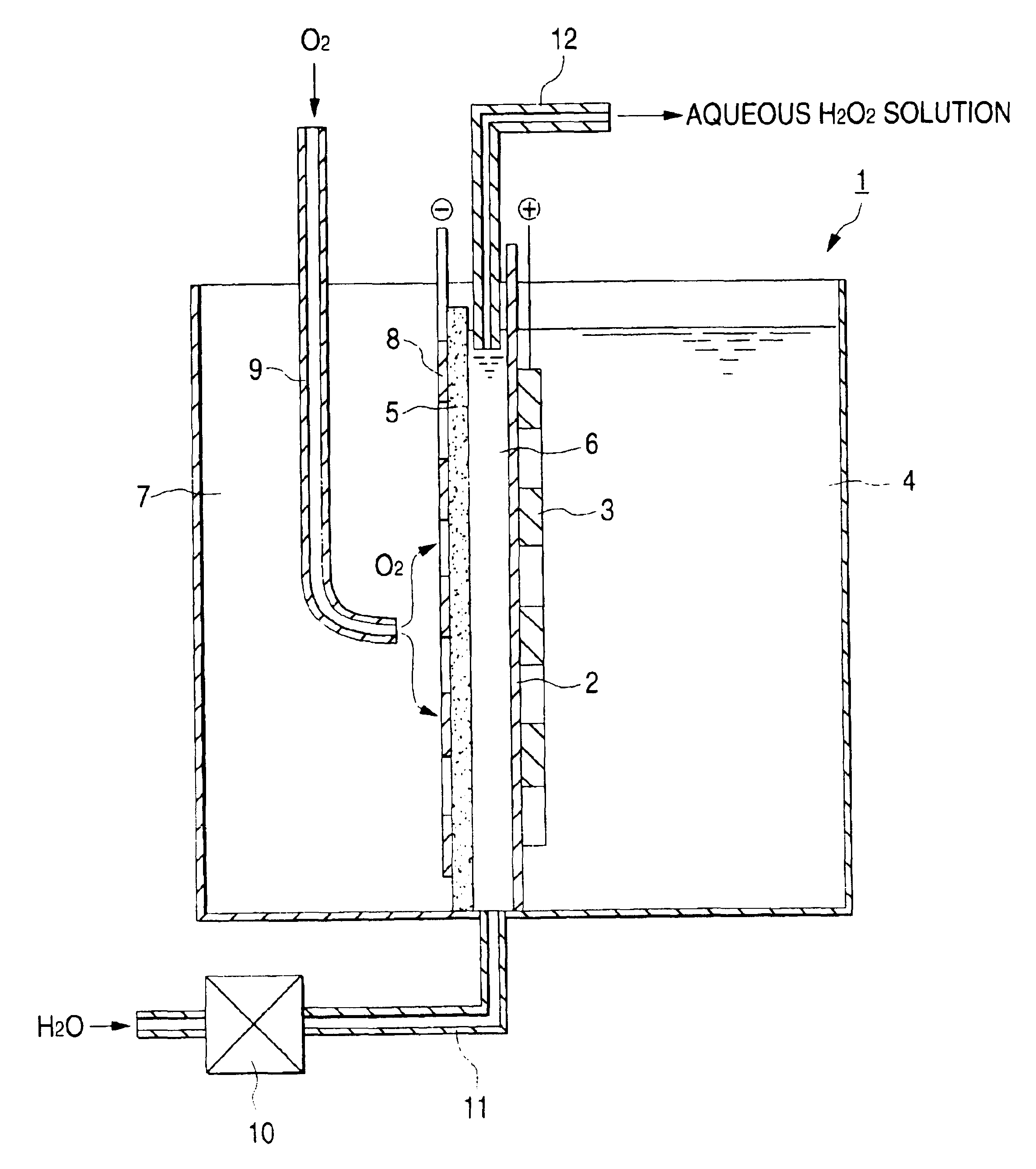
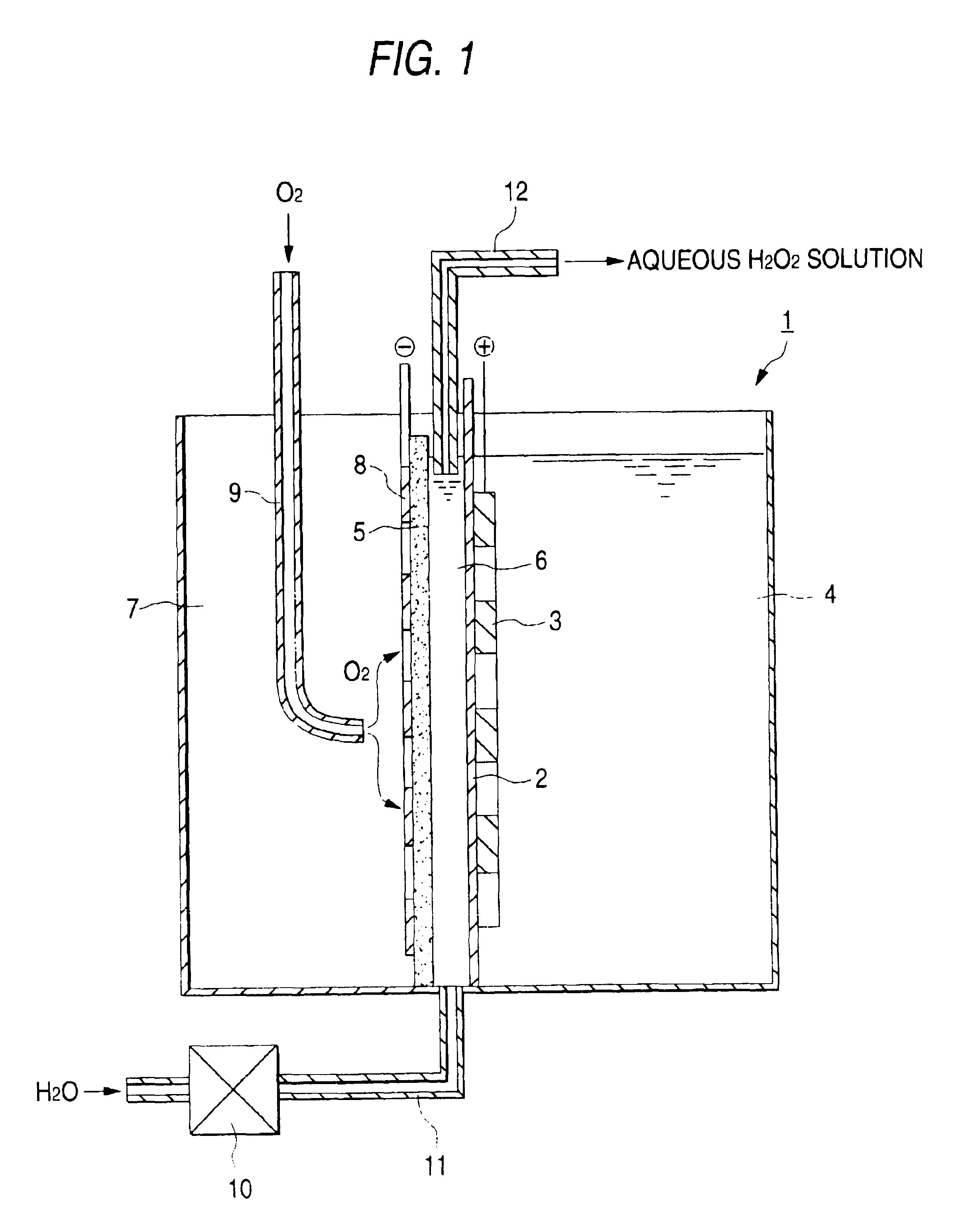
The anode was placed into intimate contact with an ion-exchange membrane (Nafion 117, manufactured by E.I. du Pont de Nemours & Co.). The feeder-bearing oxygen gas diffusion cathode was disposed so as to result in an electrode spacing of 3 mm to fabricate an electrolytic cell having the structure shown in the FIGURE which had a height of 25 cm and an area effective for electrolysis of 125 cm.sup.2.

On the other hand, tap water was softened with an ion-exchange membrane, and sodium sulfate was diss...

example 2

An electrolytic cell was fabricated under the same conditions as in Example 1, except that the ion-exchange membrane was omitted. While the aqueous sodium sulfate solution prepared in Example 1 continued to be supplied to the electrolytic cell (to the region corresponding to the anode chamber and solution chamber in Example 1) at a rate of 20 ml / min, a current of 6.3 A was passed through the electrolytic cell at a temperature of 25.degree. C. As a result, the cell voltage was 12 V and an aqueous hydrogen peroxide solution having a hydrogen peroxide concentration of about 2,500 ppm was obtained through the outlet from the electrolytic cell at a current efficiency of about 40%.

This electrolytic production of hydrogen peroxide was continued for 6,000 hours. As a result, the current efficiency and the hydrogen peroxide concentration decreased to about 30% and about 2,000 ppm, respectively. However, the operation could still be continued.

example 3

An electrolytic cell was fabricated under the same conditions as in Example 1, except that a manganese dioxide electrode was used as an anode.

Tap water was softened with an ion-exchange membrane, and sodium chloride was dissolved therein in a concentration of 0.007 M to prepare an electrolytic feed solution having a conductivity of about 1 mS / cm.

This feed solution was supplied to the anode chamber and the solution chamber at a rate of 10 ml / min and air was fed to the gas chamber at a rate of 500 ml / min. While thus supplying these feed materials, a current of 6.3 A was passed through the electrolytic cell at a temperature of 25.degree. C. As a result, the cell voltage was 12 V and an aqueous hydrogen peroxide solution having a hydrogen peroxide concentration of about 5,000 ppm was obtained through the outlet from the solution chamber at a current efficiency of about 80%. In the anode chamber, effective chlorine compounds including hypochlorite ion were produced at a current efficienc...


PUM

PropertyMeasurementUnit
concentrationaaaaaaaaaa
porosityaaaaaaaaaa
sizeaaaaaaaaaa

Abstract

An electrolytic cell and method of electrolysis for producing hydrogen peroxide at a moderate current density while preventing metal deposition on the cathode surface. A feed water from which multivalent metal ions have been removed and in which a salt of a univalent metal, e.g., sodium sulfate, has been dissolved in a given concentration is prepared with an apparatus for removing multivalent metal ions and dissolving a salt in low concentration. The feed water is supplied to an electrolytic cell. Even when electrolysis is continued, almost no deposition of a hydroxide or carbonate occurs on the cathode because multivalent metal ions are not present in the electrolytic solution. Due to the dissolved salt, a sufficient current density is secured to prevent an excessive load from being imposed on the electrodes, etc. Thus, stable production of hydrogen peroxide is possible over a long period of time.

Description

The present invention relates to an electrolytic cell and process for producing hydrogen peroxide at a high current efficiency.DESCRIPTION OF THE RELATED ARTThere is concern about adverse influences of pollution by industrial and household wastes, such as air pollution and the deterioration of water quality in rivers and lakes, on the environment and the human body, and there is an urgent need to take technical measures to eliminate those problems. For example, a chemical such as chlorine has been used in the treatment of drinking water, sewage, and wastewater for the purpose of decoloring, COD reduction, and sterilization. However, since large chlorine doses result in the generation of hazardous substances, e.g., environmental hormones (exogenous endocrine disruptors) and carcinogenic substances, the addition of chlorine tends to be prohibited.The incineration of wastes can generate carcinogenic substances (dioxins) in the emission gas depending on combustion conditions and thereby...

Claims


Application Information

Patent Timeline
Patent Type & Authority Patents(United States)
IPC IPC(8): C25B1/30C25B1/00C01B15/027C25B15/08
CPCC25B1/30
Inventor UNO, MASAHARUWAKITA, SHUHEISEKIMOTO, MASAOFURUTA, TSUNETONISHIKI, YOSHINORI
Owner DE NORA PERMELEC LTD
Why Eureka
Try Eureka