
Backplane system using incident waveform switching

a waveform switching and backplane technology, applied in the field of system interfaces for backplane technology, can solve the problems of inability to meet the needs of dedicated irq lines, too slow, and inability to meet the needs of edge connectors,

Inactive Publication Date: 2004-12-28
SEMICON COMPONENTS IND LLC
View PDF18 Cites 12 Cited by
  • Summary
  • Abstract
  • Description
  • Claims
  • Application Information

AI Technical Summary

Benefits of technology

These and other objects are achieved in the present invention by establishing a backplane bus driver arrangement that produces incident wave switching rather than reflective wave switching. That is, the driver establishes a voltage swing or step that is of sufficient amplitude to ensure that all receivers coupled to the bus recognize that swing as a valid change of logic state on the first signal edge. Presently, much of the signal propagation associated with PCI architecture is generated at the board level through CMOS, TTL, and LVTTL drivers and receivers, and their equivalents. Those drivers / receivers generate voltage swings that exceed 1.5 volts in order to produce changes in logic state. When those swing requirements are combined with existing bus impedances related to the connector traces, and the variations in impedances associated with different load impedances, impedance mismatches result. That is particularly the case as increasingly faster switching rates are desired. Those faster switching rates further exacerbate the impedance mismatches, thereby increasing signal noise. The resultant noise must be accounted for so that there is no confusion on the bus. This is achieved by reducing the wave path defined by the bus traces so that the noise settles in time to provide a voltage on the bus that is sufficient to provide a clear logic signal to all receivers on the bus. The path reduction limits the number of connector slots on the motherboard.
As indicated, the driver used in the present invention must be capable of generating incident wave switching. One type of circuit for doing so is described in pending U.S. patent application Ser. No. 09 / 132,595 of Oscar Freitas, filed Aug. 11, 1998, and assigned to a common assignee. The content of that application is incorporated herein by reference. One example of such a driver is the GTLP transceiver, such as model GTLP18T612 offered by Fairchild Semiconductor of South Portland, Me. This driver (transceiver) slows the signal transition enough to minimize noise significantly and therefore avoids reflections.
In addition to the introduction of an incident wave-switching driver, the present invention includes a fairly specific backplane layout to assist in minimizing impedance mismatches. Specifically, the stub impedance (impedance of the connectors for connecting a daughter card to the backplane bus), and backplane impedance. In general, the present invention shortens the connector stubs (thereby reducing their impedances), while maintaining the backplane impedance at or near its current typical value. The present invention relates to selecting appropriate values for those characteristics of the layout and coupling that with suitable incident wave driver technology to increase the number of slots available on a cPCI backplane or PCI / PCI-X motherboard layout without compromising signal integrity or throughput. It further includes resolution of appropriate signal clocking to minimize clock skew.

Problems solved by technology

Several communication hardware protocols have been developed, a number of which have been or are being phased out as being inadequate to support the faster signal exchange rates and increased bandwidth required by newer applications.
Unfortunately, it is designed to run at the relatively slow ISA rate of 8 MHz clocking.
In today's computing world, that is often too slow.
Since motherboards are configured with only a limited number of IRQ lines, any interface architecture that requires dedicated IRQ lines is necessarily limited.
While the PCI design is an improvement on ISA, it has a history of problems with edge connectors, poor thermal characteristics, and limited interface (input / output--I / O) capability.
In fact, PCI backplane configuration is limited to only four slots.
Unfortunately, while providing more slot availability, PCI-X continues to suffer from the same problems associated with PCI.
Because of interconnection limitations associated with the PCI architectures, there are limits on the number of peripheral devices that may be coupled together.
Bridging together two PCI-based backplanes may increase slot capacity; however, that simply increases the size / number of the computer device required to establish desired functionality.
It also introduces its own latency and transmission complications.
This round trip delay physically limits the backplane to the number of slot connections it can have for a given clock frequency.
When those swing requirements are combined with existing bus impedances related to the connector traces, and the variations in impedances associated with different load impedances, impedance mismatches result.
Those faster switching rates further exacerbate the impedance mismatches, thereby increasing signal noise.
Unfortunately, it is a common limitation since existing drivers / receivers requiring such reflections are in common commercial use.
Specifically, variations in capacitance, inductance, and resistance of the bus and the receiver connections affect whether that form of switching is achieved.
For that reason, it would be difficult to conveniently convert those processes to substitute incident wave drivers that would be compatible with the backplane layout improvements described.

Method used


Image

  • Backplane system using incident waveform switching
  • Backplane system using incident waveform switching
  • Backplane system using incident waveform switching

Examples


Embodiment Construction

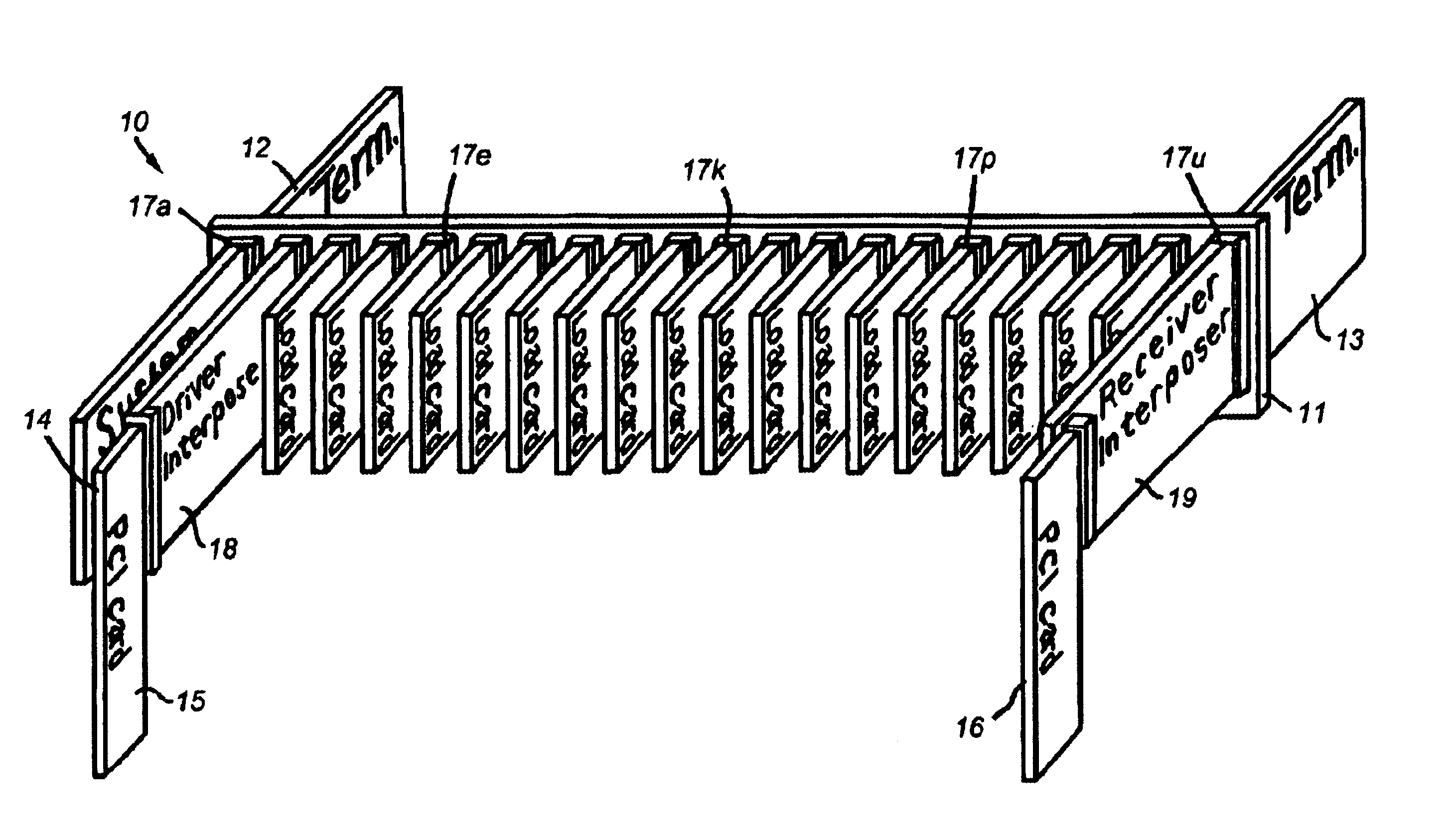
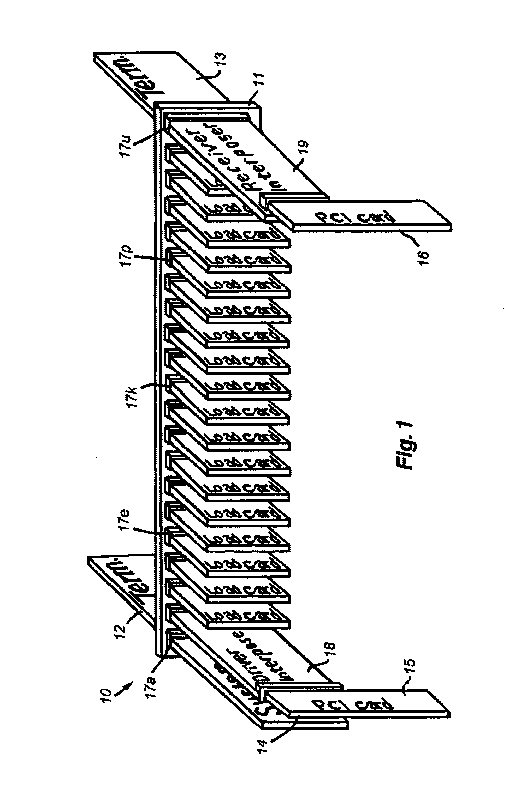
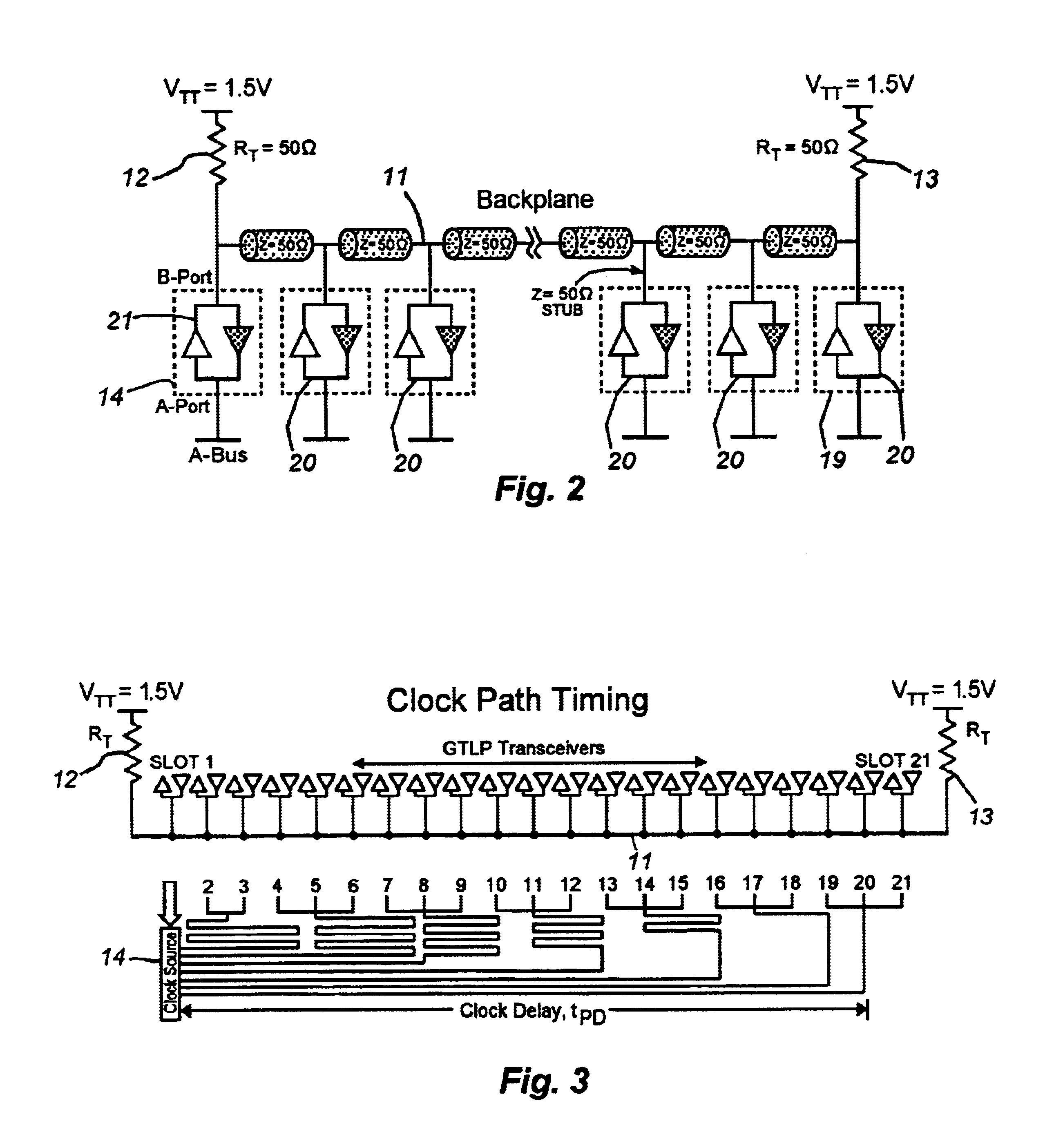
A backplane system 10 of the present invention is shown in FIG. 1. The system 10 includes a backplane bus 11 having matched impedance terminations 12 and 13 on the back or south side of the bus 11. The impedance values of the terminations 12 and 13, the impedance values of the slot connectors identified herein, and the impedance values of the backplane bus traces 11, together provide the backplane impedance of the system 10. The impedance terminations 12 and 13 are coupled to a supply rail that establishes the maximum swing potential of the backplane bus 11. The system further includes a system clock card 14 that generates the clocking scheme for each of one or more of a plurality of peripheral devices provided on daughter cards such as near card 15 and far card 16. Each card includes one or more integrated circuits for performing functions of interest regulated by one or more central processing units tied to the backplane bus 11. The cards 15 and 16 are of the type that may be inse...


PUM


Abstract

A backplane bus system and related method for increasing the throughput of cPCI-specified backplane architectures. The system includes an interposer card for transforming reflective-wave switching into incident-wave switching. Establishing incident-wave switching on the bus along with careful slot pitch and impedance layout increases the rate at which the voltage amplitude observed by all receivers connected to the bus is sufficient to produce a change of state on the first signal propagation down the bus. Most existing peripherals are configured with transceivers that produce reflective-wave switching. The present system includes an interposer card to transform that switching into incident-wave switching. A preferred transceiver for doing so and that is implemented on the interposer card is a GTLP transceiver. A state machine is employed to regulate operation of the incident-wave switching transceiver. The system may be used to permit implementation of as many as 21 slots on a conventional cPCI backplane.

Description

1. Field of the InventionThe present invention relates to system interfaces for backplane technology. More particularly, the present invention relates to bridges and switching systems for establishing transmission interfaces among circuit boards or cards installed in computing device backplanes. The system enables the insertion of a greater number of cards in a backplane topology than has heretofore been possible.2. Description of the Prior ArtStandards have been established for the architecture of the hardware employed to enable the exchange of electrical signals among processing devices. The processing devices include integrated circuit systems built on and using printed circuit boards by an increasingly wide array of suppliers. The architecture standards ensure that the various devices will, in fact, be able to communicate with one another as well as with central processing units that control the operation of such peripheral devices. These peripherals include, but are not limited...

Claims


Application Information

Patent Timeline
Patent Type & Authority Patents(United States)
IPC IPC(8): G06F13/00H05K7/10H05K7/14
CPCH05K7/1459
Inventor KLEM, R. CRAIGPOIRIER, CARL R.
Owner SEMICON COMPONENTS IND LLC
Learn More