Sinter-bonded direct pin connections for inert anodes

a direct pin connection and inert anode technology, applied in the direction of electrolysis components, manufacturing tools, separation processes, etc., can solve the problems of cracks, diffusion bonding, mechanical connection failure, etc., to reduce materials and assembly costs, improve electrical joint resistance, and avoid cracks

Inactive Publication Date: 2005-02-15
ARCONIC INC
View PDF11 Cites 41 Cited by
  • Summary
  • Abstract
  • Description
  • Claims
  • Application Information

AI Technical Summary

Benefits of technology

The preferred connection design alleviates cracked anodes due to differential thermal growth, provides a stable electrical joint resistance that does not degrade ...

Problems solved by technology

Despite the common usage of carbon as an electrode material in practicing the process, there are a number of disadvantages to its use, and so, attempts are being made to replace them with inert (not containing carbon) anode electrodes made of for example a ceramic, metal-ceramic “cermet” or metal containing material.
Although ceramic and cermet electrodes are capable of producing aluminum having an acceptably low impurity content, they are susceptible to cracking during cell start-up when subjected to temperature differentials on the order of about 900° C.-1000° C. In addition, ceramic components of the anode support structure as...

Method used


Image

  • Sinter-bonded direct pin connections for inert anodes
  • Sinter-bonded direct pin connections for inert anodes
  • Sinter-bonded direct pin connections for inert anodes

Examples


example 1

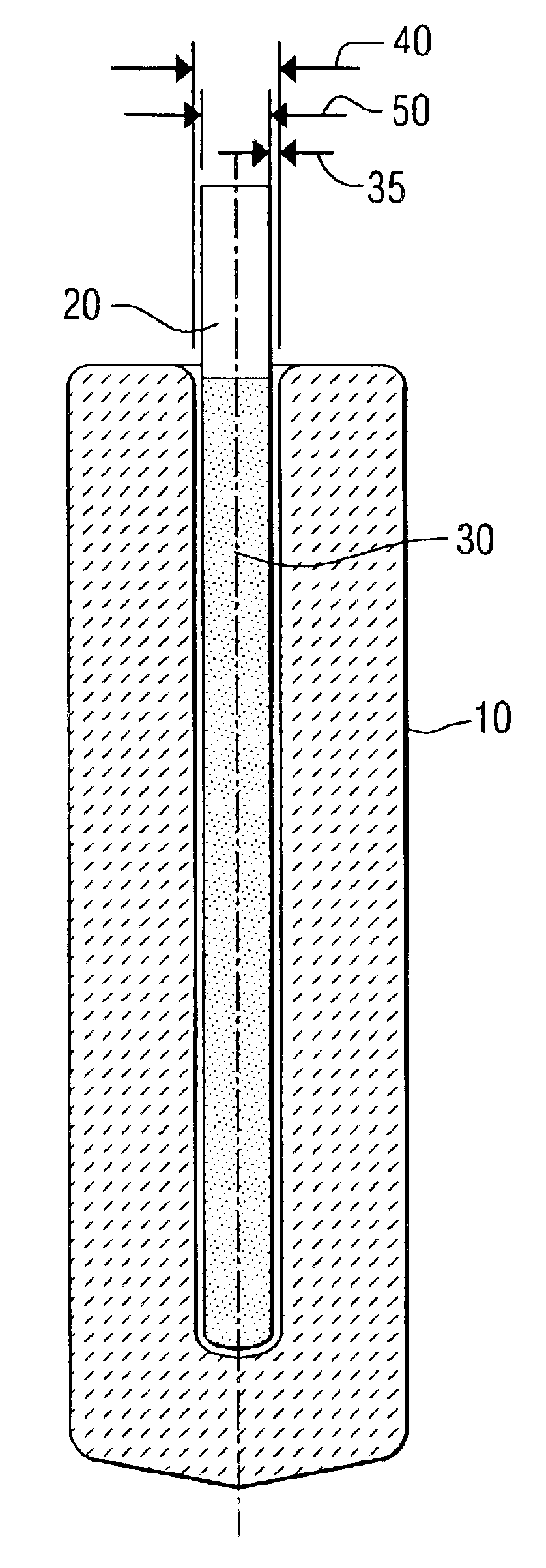
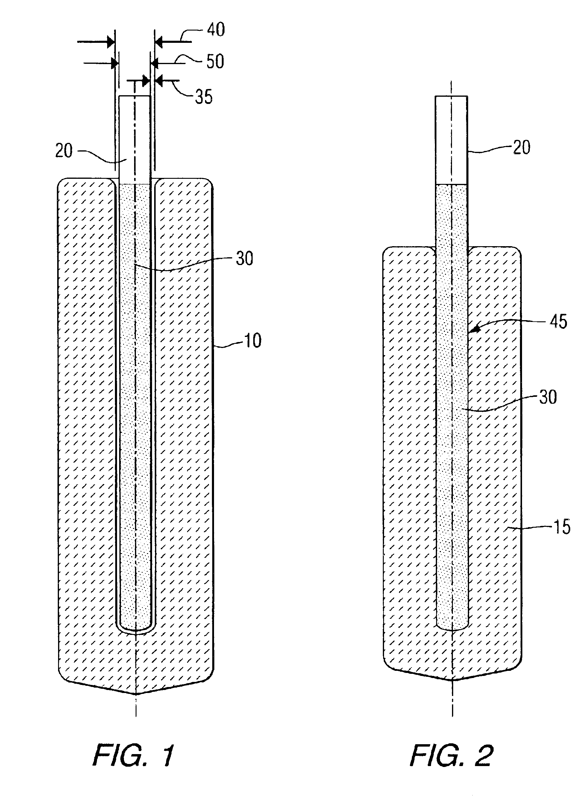
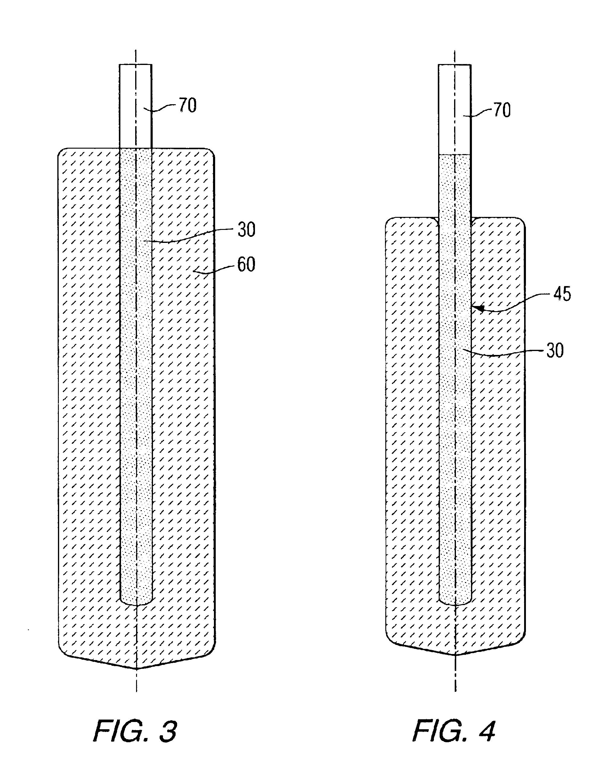
An electrode assembly was prepared using a hollow inert anode, a metal conductor comprised of Inconel 600 alloy, and a coating on the conductor of a copper-nickel alloy. The anode was isostatically pressed from powder to have a hollow opening of 0.813 inches (2.06 cm) diameter. Anode porosity after pressing was about 40 vol. %. The pin diameter was 0.75 inches (1.9 cm) and the surface additive coating was applied as a flame spray to a thickness of 0.030 inches (0.076 cm) around the pin. The coating composition was 67.8 wt. % copper, 30.6 wt. % nickel with the balance Fe, Mn, Ti and other impurities. The anode was sintered at 1250° C. in an argon atmosphere until a full density, about 1 vol. % to 5 vol. % porosity was achieved. The concurrent shrinkage allowed the sintered anode material to come in contact with the pin and coating and establish a continuous, coherent electrical contact at the interface. The bonding was good enough to serve as a mechanical support. Final anode dimensi...

example 2

A series of 24 anodes were produced and tested in a statistically-designed matrix of experiments. The electrode assemblies were prepared using hollow inert anodes, a metal conductor, and an additive coating on the conductor. The conductor comprised a copper-nickel alloy. The anode was isostatically pressed from powder to have a hollow opening of various diameters. The coating composition was 67.8 wt. % copper, 30.6 wt. % nickel with the balance of Fe, Mn, Ti and other impurities. The anodes were sintered at 1250° C. in an argon atmosphere until a full density was achieved, about 1 vol. % to 5 vol. % porosity. The concurrent shrinkage allowed the sintered anode material to come in contact with the pin and coating and establish a continuous, coherent electrical contact at their interface. The bonding was good enough to serve as a mechanical support. Final anode dimensions were 6 inches long (15.24 cm) by 3 inches (7.62 cm) in diameter, with a hemispherical bottom.

The anodes were isost...


PUM

PropertyMeasurementUnit
Temperatureaaaaaaaaaa
Fractionaaaaaaaaaa

Abstract

A sintered electrode assembly is made of an inert electrode (15) containing a sealed metal conductor (20) having a surface feature (30) such as a coating or wrapping which aids in bond formation with the inert electrode (15) at their interface (45), where the metal conductor (20) is directly contacted by and is substantially surrounded by the inert electrode (15) without the use of metal foam or metal powders.

Description

FIELD OF THE INVENTIONThis invention relates to low resistance electrical connections between a solid metallic pin conductor and the interior of a ceramic or cermet inert anode used in the production of metal, such as aluminum, by an electrolytic process.BACKGROUND OF THE INVENTIONA number of metals including aluminum, lead, magnesium, zinc, zirconium, titanium, and silicon can be produced by electrolytic processes. Each of these electrolytic processes employs an electrode in a highly corrosive environment.One example of an electrolytic process for metal production is the well-known Hall-Heroult process producing aluminum in which alumina dissolved in a molten fluoride bath is electrolyzed at temperatures of about 960° C.-1000° C. As generally practiced today, the process relies upon carbon as an anode to reduce alumina to molten aluminum. The carbon electrode is oxidized to form primarily CO2, which is given off as a gas. Despite the common usage of carbon as an electrode material ...

Claims


Application Information

Patent Timeline
IPC IPC(8): C25C7/02C25C3/12C25C7/00C25C3/00
CPCC25C3/12C25C7/025Y10T29/53204Y10T29/532
Inventor D'ASTOLFO, JR., LEROY E.
Owner ARCONIC INC
Why Eureka
Try Eureka