
Photopolymerized sol-gel column and associated methods

Inactive Publication Date: 2005-03-15
THE BOARD OF TRUSTEES OF THE LELAND STANFORD JUNIOR UNIV
View PDF49 Cites 76 Cited by
  • Summary
  • Abstract
  • Description
  • Claims
  • Application Information

AI Technical Summary

Benefits of technology

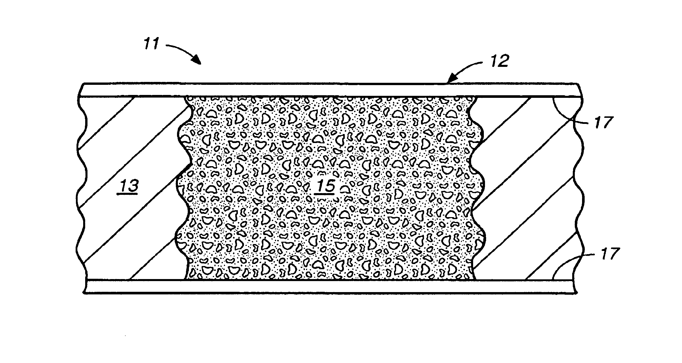
A separation column includes a separation channel and a fritless separation medium in the channel. The medium includes a porous matrix, and the porous matrix includes a metal organic polymer. The polymer may be a photopolymer. In the preferred embodiment, the porous matrix contains no chromatographic particles. The porous matrix may be used to both preconcentrate and separate analytes without chromatographic particles. The separation column allows for the concentration and separation of larger volumes of analytes than a separation column with chromatographic particles.
A method of preparing a monolith is provided. A separation column is provided. A mixture is introduced into the separation column. The mixture includes a metal organic compound. The mixture is irradiated to form a solid, porous matrix via photoinitiated polymerization. Thus, a fritless separation medium is formed in the separation column. In the preferred embodiment, the porous matrix contains no chromatographic particles. Preparation of a fritless separation medium without chromatographic particles is simpler than preparing a separation medium with a frit or chromatographic particles. The porous matrix may be used both to preconcentrate and separate analytes.
The photochemical route to the preparation of the porous matrix has many advantages: (1) short preparation time, (2) control of the pore size, (3) control over the placement and length of the porous matrix, (4) high mechanical strength, and (5) avoidance of high temperatures that lead to cracking.
A method of separating a sample of analytes is provided. A separation column including a separation channel and a fritless separation medium in the channel is provided. The medium includes a porous matrix, and the porous matrix includes a metal organic polymer, such as a photopolymer. In the preferred embodiment, the porous matrix contains no chromatographic particles. A sample of analytes carried in a solution is introduced through the column. The medium concentrates the analytes on the column. A solution is caused to flow through the column, thereby separating and eluting the analytes. The medium both preconcentrates and separates the analytes. In addition to the effect exerted by the medium, preconcentration can be further enhanced by a solvent gradient or sample stacking.

Problems solved by technology

Although CEC has been applied in many different areas, packed-column preparation and low-detection sensitivity remain challenges of this technique.
One disadvantage of packed columns is the fabrication of porous frits of controlled pore sizes, lengths, and high mechanical stabilities.
A major challenge in CEC techniques is the detection of samples containing analytes at low concentration.
The lack of sensitivity at low concentration stems from the small sample volume and the short optical path length for on-line detection.
Schemes such as solvent-solvent extraction and solid-phase extraction are often very tedious and time-consuming.

Method used


Image

  • Photopolymerized sol-gel column and associated methods
  • Photopolymerized sol-gel column and associated methods
  • Photopolymerized sol-gel column and associated methods

Examples


example 1

Materials and Chemicals. Fused-silica capillaries (75-μm i.d.×365-μm o.d.) were purchased from Polymicro Technologies, Phoenix, Ariz. Methacryloxypropyltrimetoxysilane (MPTMS) was purchased from Gelest, Tullytown, Pa. and Sigma-Aldrich, Milwaukee, Wis. and was used without purification. HPLC-grade toluene, phenanthrene, pyrene, alkyl benzenes, alkyl phenyl ketones, and steroids were purchased from Sigma-Aldrich, Milwaukee, Wis. Irgacure 1800 was received from Ciba, Tarrytown, N.Y.

Instrumentation. A Beckman P / ACE 2000 capillary electrophoresis instrument with a UV-absorbance detector was used to carry out all CEC experiments. An XL-1500 UV cross-linker, available from Spectronics Corp., Westbury, N.Y., equipped with six 15 W blacklight tubes of predominantly 365-nm wavelength was used to irradiate the reaction solutions. Scanning electron microscopy (SEM) analyses were performed on a Philips SEM 505 scanning electron microscope, available from Eindhoven, Netherlands.

Polymerization Pr...

example 2

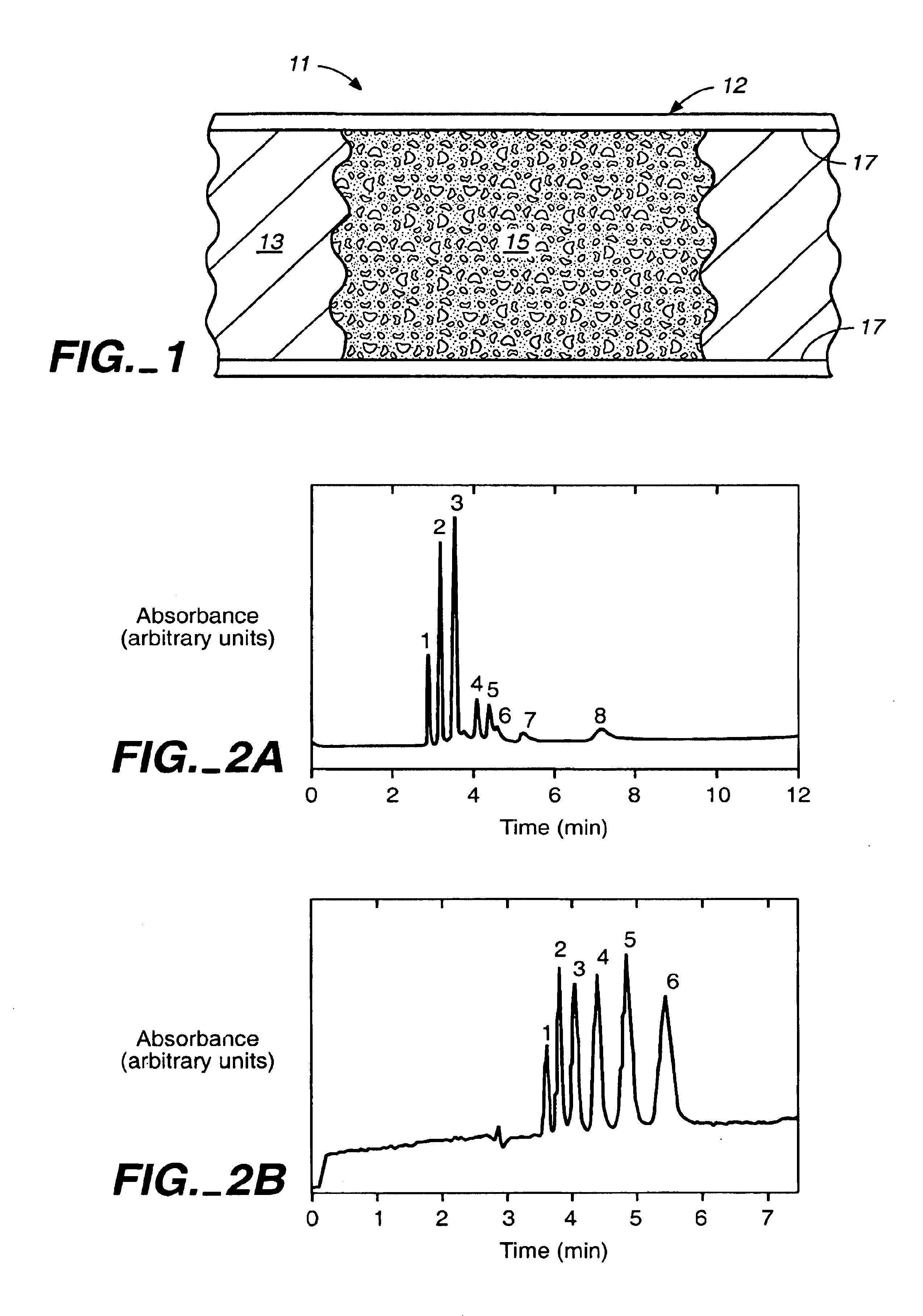
The separation column was prepared as described in Example 1. A mixture of 1:1 hexane / toluene was used for the porogen. The separation column had a separation performance similar to that of a separation column made with 80 / 20 toluene / reaction solution. A column efficiency of 68,000 plates / m (RSD 7.0%, n=5) for thiourea and an electroosmotic flow (EOF) velocity of 3.7 cm / min was obtained.

example 3

A mixture of 375 μL of MPTMS and 100 μL of 0.12 M hydrochloric acid was stirred for thirty minutes at room temperature. 27 parts of this mixture were combined with 73 parts of toluene to give 200 μL of the final solution. 5% by weight of the final solution of the photoinitator Irgacure 1800 was added, and the resulting sol-gel solution was stirred for five minutes before use. A 75-μm i.d.×365-μm o.d. fused silica capillary was filled with the sol-gel solution, and the separation column was exposed to UV light in a Spectrolinker Xl-1500 at 365 nm to affect photopolymerization. The polymerization length of the porous matrix was controlled by removing a 15-cm strip of the polyimide coating of the capillary prior to irradiation for five minutes. Unreacted reagents were flushed with ethanol. The total length of the capillary was 25.6 cm (18.8 cm from inlet to the detector window). The resulting column was conditioned with the separation solution prior to use.

All electrophoresis experimen...


PUM

PropertyMeasurementUnit
Volumeaaaaaaaaaa
Volumeaaaaaaaaaa
Volumeaaaaaaaaaa

Abstract

A separation column and a method of making the separation column are provided. The separation column includes a separation channel and fritless separation medium in the channel. The separation medium includes a porous matrix, and the porous matrix includes a metal organic polymer, such as a photopolymer. The separation medium can be used to separate a sample of analytes.

Description

BACKGROUND OF THE INVENTIONThe invention relates in general to a separation column, and, in particular, to a photopolymerized sol-gel column.Capillary electrochromatography (CEC) has been regarded as a very promising analytical separation technique that combines the efficiency of capillary zone electrophoresis (CZE) with the selectivity of liquid chromatography. Although CEC has been applied in many different areas, packed-column preparation and low-detection sensitivity remain challenges of this technique. Capillary columns containing small silica packings have been the mainstay of CEC. One disadvantage of packed columns is the fabrication of porous frits of controlled pore sizes, lengths, and high mechanical stabilities. In response to frit fabrication problems, surface-functionalized open-tubular capillary columns and monolithic capillaries are being developed as variants of packed capillary columns. Monolithic capillary columns have received much attention because of the advanta...

Claims


Application Information

Patent Timeline
IPC IPC(8): G01N30/00G01N30/52B01D15/08B01J20/281
CPCB01J20/281G01N30/48G01N2030/528B01J2220/54B01J20/286B01J20/3208B01J20/3259B01J2220/86
Inventor ZARE, RICHARD N.DULAY, MARIA T.QUIRINO, JOSELITO P.BENNETT, BRYSON
Owner THE BOARD OF TRUSTEES OF THE LELAND STANFORD JUNIOR UNIV
Learn More