Magnetic carbon nanotube

a carbon nanotube and magnetic technology, applied in the field of carbon nanotubes, can solve the problems of affecting the strength of the bond between, affecting the stability of the bond, and affecting the stability of the bond, and achieve the effect of high thermal stability

Inactive Publication Date: 2005-04-12
HITACHI LTD
View PDF8 Cites 13 Cited by
  • Summary
  • Abstract
  • Description
  • Claims
  • Application Information

AI Technical Summary

Benefits of technology

It is an object of the present invention to provide a carbon nanotube which exhibits ferromagnetism without a ferromagnetic metal being attached thereto, and which possesses a high thermal stability.

Problems solved by technology

Unfortunately, a composite material, which is composed of a carbon nanotube and a ferromagnetic metal, has a problem concerning the strength of the bond between them.
If a carbon nanotube with iron as a ferromagnetic metal is used as a sensing probe for an MFM, there is the possibility that iron particles will drop off, or that the probe will be broken, when the probe is brought into contact with a sample.
Such a problem would occur when the shape of the sample is measured by use of the tapping mode, in which the sample is tapped with a vibrating probe, or by use of the contact mode, in which the sample is scanned with a probe in contact with it.
There is another problem which relates to the temperature at which the probe is used.
For example, a probe with iron as a ferromagnetic metal has difficulties in the measurement of magnetism at high temperatures exceeding 770° C., which is a Curie point of iron.
It is difficult to carry out stable measurement at high temperatures, even under the Curie point, because the amount of magnetization usually decreases with temperature, thereby resulting in noise.
The foregoing problem also arises when the probe comes into contact with a sample, thereby generating heat.

Method used


Image

  • Magnetic carbon nanotube
  • Magnetic carbon nanotube
  • Magnetic carbon nanotube

Examples


embodiment 1

[Embodiment 1]

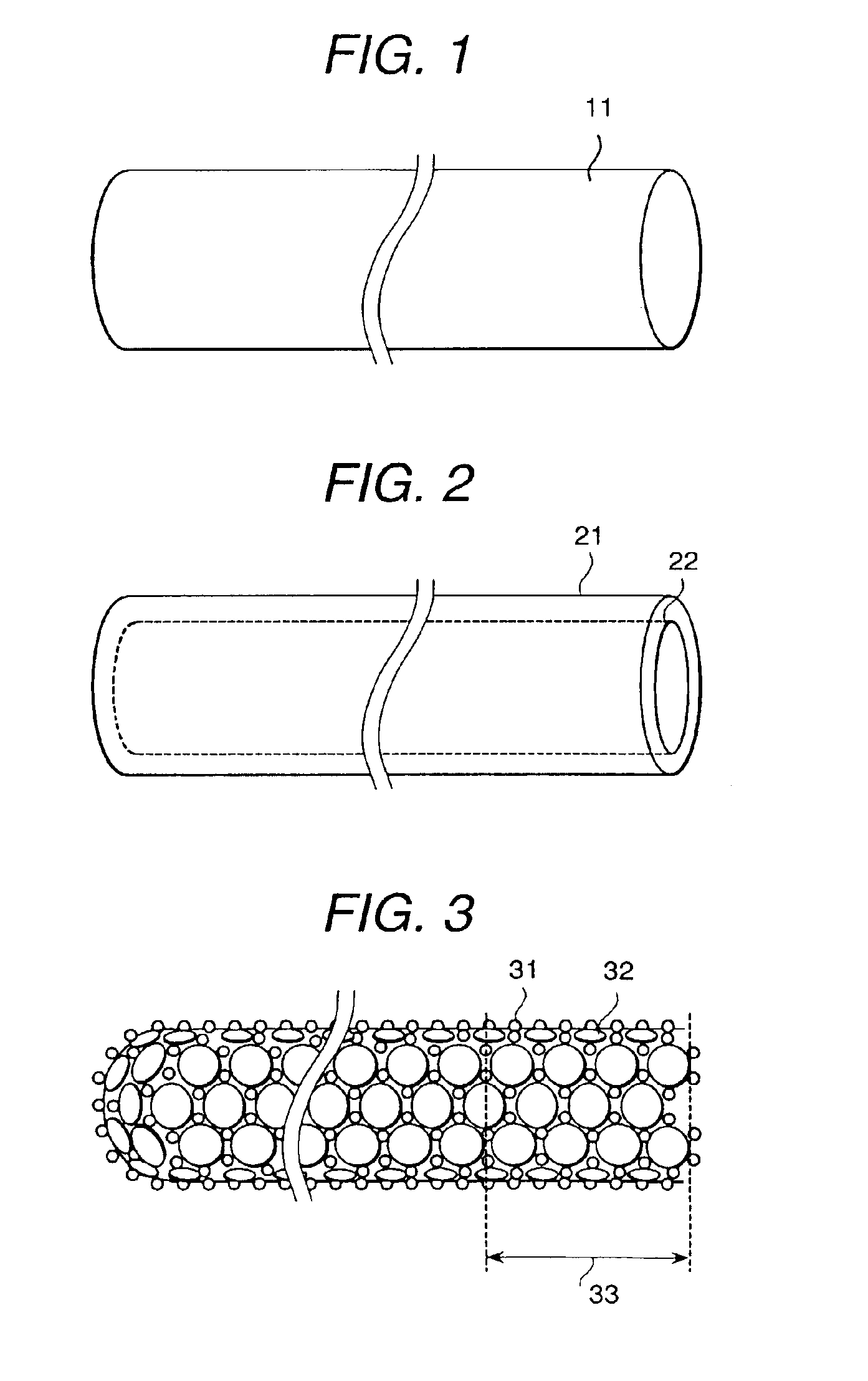
FIGS. 1 and 2 are schematic diagrams showing a carbon nanotube. FIG. 1 shows a carbon nanotube having a cylindrical shape, which is composed of a single graphite layer 11. It is referred to as a single walled carbon nanotube (SWCNT). FIG. 2 shows a carbon nanotube, having a cylindrical shape, which is composed of an outer graphite layer 21 and an inner graphite layer 22. It is referred to as a multi-walled carbon nanotube (MWCNT). Incidentally, a MWCNT includes not only those structures composed of two walls, but also those structures composed of three or more walls. In addition, some kinds of SMCNT and MWCNT have their ends covered with a semispherical cap composed of five-membered rings. Such a cap is called a “fullerene cap”.

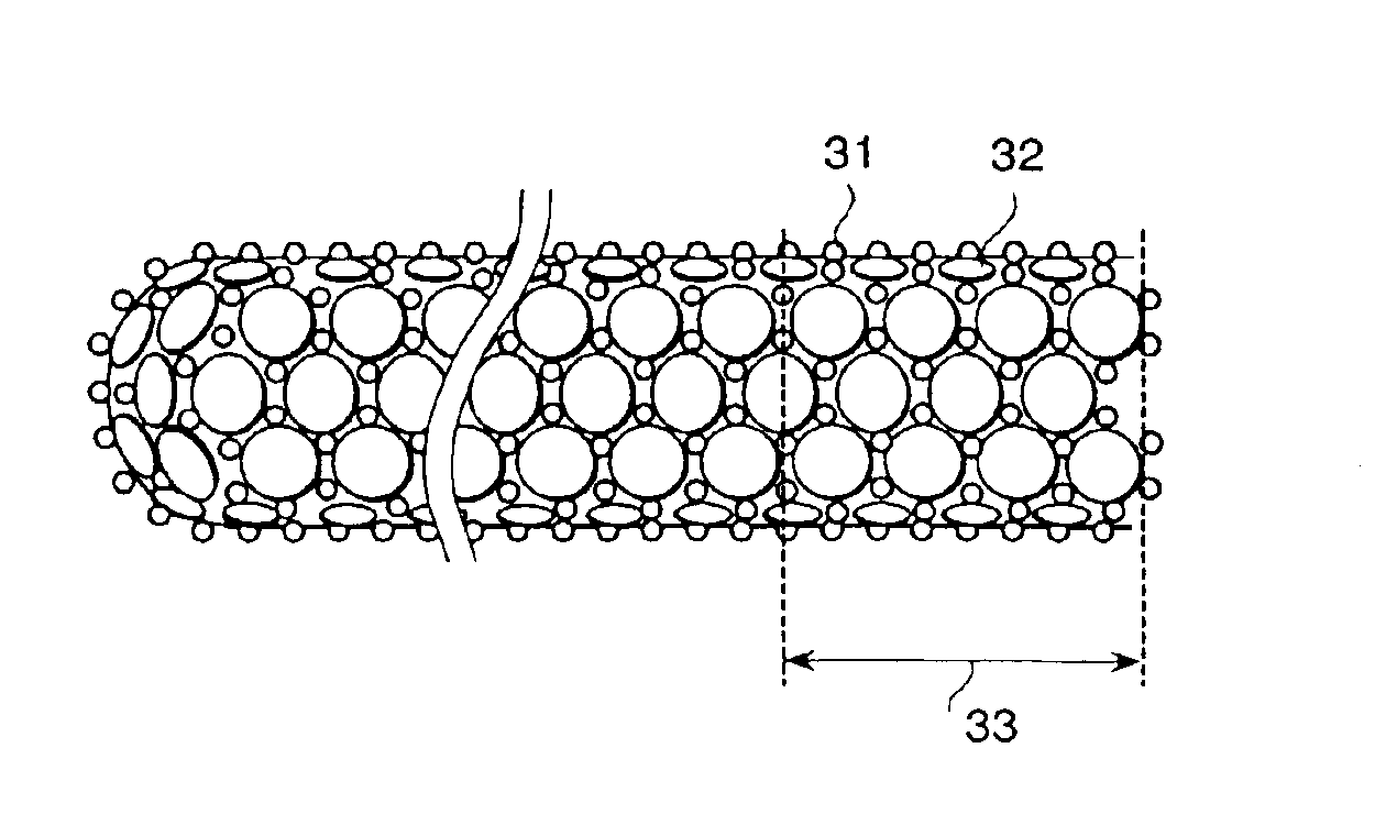
FIG. 3 is a schematic diagram showing a carbon nanotube pertaining to the present invention. This carbon nanotube has some of its constituent carbon atoms 32 replaced by doped nitrogen atoms 31, and it possesses a carbon-nitrogen mixed region 33...

embodiment 2

[Embodiment 2]

FIG. 6 is a schematic diagram showing a magnetic force microscope whose magnetic probe 65 is the carbon nanotube represented by Embodiment 1. The magnetic force microscope is made up of a laser emitter 53, a reflecting mirror 62, an optical detector 61, a cantilever 64, and a magnetic probe 65 that is attached to the cantilever 54, said magnetic probe 65 being the carbon nanotube of Embodiment 1. Incidentally, the specimen 66 being observed under the magnetic force microscope may be heated by a heater 67, if necessary.

The following method is used to attach the carbon nanotube 65 to the cantilever 64. First, a cluster of carbon nanotubes 65 is brought into contact with the tip of the cantilever 64. The resulting assemblage is placed in a focused ion beam (FIB) apparatus. A gas containing a tungsten compound is blown toward the base of the carbon nanotube in contact with the tip of the cantilever 64 during irradiation with a gallium ion beam, so that the following reacti...

embodiment 3

[Embodiment 3]

This Embodiment demonstrates the use of a carbon nanotube (pertaining to Embodiment 1) as the main magnetic pole of a head for a vertical magnetization memory. The head, which is schematically shown in FIG. 7, has an exciter 72 to generate a magnetic field that constitutes a closed magnetic circuit passing through the carbon nanotube 71, serving as the main magnetic pole, the recording medium 70, and the auxiliary magnetic pole 73.

The head for the vertical magnetization memory has the property that its recording / reproducing characteristics depend largely on the tip size of the main magnetic pole. The tip should have as small a radius of curvature as possible. Since the carbon nanotube in this embodiment has a high aspect ratio and also exhibits ferromagnetism, it permits high-density vertical magnetization in a memory medium. A carbon nanotube without a ferromagnetic metal cap may also be used as the main magnetic pole. It has no possibility of breakage and of metal pa...


PUM

PropertyMeasurementUnit
Curie pointsaaaaaaaaaa
Curie pointaaaaaaaaaa
Temperatureaaaaaaaaaa

Abstract

A carbon nanotube which exhibits ferromagnetism without a ferromagnetic metal imparted thereto and also has high thermal stability is provided. The carbon nanotube is characterized by being doped with nitrogen (which differs from carbon in valence electron) such that the doped nitrogen is segregated in a strip form at one end of the carbon nanotube. The thus doped nitrogen causes the carbon nanotube to have a difference in electron density and to exhibit ferromagnetism. The present invention makes it possible to provide a carbon nanotube exhibiting ferromagnetism without the necessity of imparting any magnetic metal thereto.

Description

BACKGROUND OF THE INVENTIONThe present invention relates to a carbon nanotube and to an apparatus provided therewith.A carbon nanotube is a microscopic material composed mainly of carbon. It has a very large aspect ratio, with its diameter being a few nanometers and its length being hundreds to thousands of nanometers. Therefore, it is expected to be applied to scanning probe microscopes (SPM), typified by atomic force microscopes (AFM) and scanning tunneling microscopes (STM), which depend for their resolution largely on the radius of curvature of the tip of the sensing probe.Among SPMs, there is a magnetic force microscope (MFM) which employs a ferromagnetic sensing probe to read a magnetic gradient in a sample. When a carbon nanotube, which is a paramagnetic substance having the stable s-p bond, is to be applied to an MFM, it needs to have ferromagnetism. This objective can be achieved by attaching, in any way, a ferromagnetic metal to the tip or inside of the carbon nanotube. Th...

Claims


Application Information

Patent Timeline
Patent Type & Authority Patents(United States)
IPC IPC(8): C01B31/00C01B31/02G11B5/127H01F1/00G11B5/187G11B5/00G11B9/00G01Q60/54G01Q60/56G01Q70/12G01Q80/00
CPCB82Y10/00G01Q70/12B82Y30/00B82Y40/00C01B31/0226C01B31/0253G11B5/1278H01F1/0072G01Q60/54C01B2202/02C01B2202/06C01B2202/20G11B5/127G11B5/187G11B9/1409G11B2005/0002Y10S977/742Y10S977/838Y10S428/90Y10T428/30Y10T428/2958Y10T428/2991Y10T428/31Y10T428/2933B82Y25/00C01B32/16C01B32/168C01B32/05B82B3/00
Inventor SUZUKI, SHUICHIHIDAKA, KISHIOHAYASHIBARA, MISTUO
Owner HITACHI LTD
Why Eureka
Try Eureka