Decorative laminate assembly and method of producing same

a technology of decorative laminates and laminates, applied in the field of decorative laminate assemblies, can solve the problems of reducing the aesthetically attractiveness of vinyl tiles or linoleum-like, limiting the application of existing decorative laminates, and reducing the application of adhesives to the substrate (and/or top layer), so as to achieve enhanced wear resistance qualities, avoid material, labor and equipment costs of adhesive application to the substrate, and avoid the effect of adhesive application

Inactive Publication Date: 2006-07-25
THE DILLER +1
View PDF34 Cites 54 Cited by
  • Summary
  • Abstract
  • Description
  • Claims
  • Application Information

AI Technical Summary

Benefits of technology

[0035]The aforementioned needs are addressed by a decorative laminate assembly having a decorative laminate top layer assembly. This top layer assembly includes, in descending superimposed relationship, a decorative layer and a core layer that includes PETG, or other polymeric material. Preferably, the top layer assembly also includes a wear resistant overlay layer on top of the decorative layer, and the core layer's PETG is in a sheet form. The decorative laminate assemblies of the present invention may be formed by bonding the decorative layer and PETG core layer directly to the water resistant substrate without use of an adhesive, in a single operation. Surprisingly, it has been discovered that PETG not only bonds remarkably well to the melamine resin treated (or untreated) decorative layer, but also simultaneously bonds extremely well to filled PVC composite board or cement fiberboard substrate. As such, a single-step pressing operation can be advantageously employed, and the material, labor and equipment costs for the adhesive application to the substrate (and / or top layer), and subsequent bonding operation, can be avoided. The decorative laminate assemblies of the present invention can be used for a variety of purposes, including flooring applications. When the present invention is used for flooring applications, it is preferred that the overlay layer has enhanced wear resistant qualities and that the water resistant substrate comprise PVC or cement fiberboard.

Problems solved by technology

More recently, the applications for decorative laminates have been expanded to include their use as a flooring material in lieu of more expensive real wood, stone or ceramic tile, less sanitary and rugged carpeting, as well as less aesthetically attractive vinyl tile or linoleum-like products.
However, as discussed in more detail below, existing decorative laminates are not particularly suited in applications where there is repeated or prolonged exposure to moisture and / or water due to their intrinsic hydrophilic properties.
Such existing laminates have therefore been primarily limited to residential applications having dry conditions.
However, even with the more expensive HPDL clad flooring products, and using the best grades of “moisture resistant” HDF substrate (in which the board is produced at higher resin content with more moisture resistant resins), and even sized with wax and other “repellents”, serious application restrictions and problems persist with the current generation of these most widely used flooring products when exposed to repeated or prolonged contact with moisture or water.
Simply increasing the phenolic resin content in the core sufficiently to significantly improve moisture resistance is not practical since it would result in increased resin flow and bleed-out during pressing, as well as possible resin bleed-through into the laminate surface.
Conversion to a more hydrophobic, organic solvent based modified phenolic resin is prohibited because of environmental considerations, and both alternatives are precluded because of their increased cost.
Even with such installations, flooring manufacturers and installers typically recommend inclusion of (necessarily raised) expansion joints a minimum of every 20 feet to avoid buckling of the floor with any moisture uptake, although such expansion joints are aesthetically unattractive and physically intrusive.
Accordingly, wet area installations, such as bathrooms, are not generally recommended.
These so called “floating floor” installations only help control the rate, not the total equilibrium amount, of moisture uptake from underneath the flooring panels and create the disadvantages of restricting spilled water drainage from above through the joints (thus permeating into the peripheral HDF substrate, which can cause severe swelling in those areas).
Further, such installations impart a hollow sounding, springy feel to the entire floor when walked upon.
The one important advantage of a floating floor installation, however, is that the foam inclusions act as shock absorbers and significantly improve the floor's impact resistance; the decorative laminate assembly itself having inherently very poor impact resistance if installed directly on a hard, rigid subfloor without the underlayment.
Furthermore, in areas with a high water table, such as southern Florida, where a typical house is built on a concrete slab without a basement, even old concrete transmits moisture at a rate similar to that for new concrete, with the same deleterious effects to HDF-based flooring.
While they have the prerequisite moisture resistance and dimensional stability, by their very nature, they are quite soft and easily dented by heavy or impacted objects, and decorative designs are severely restricted to abstract stone-like patterns and the like.
However, simply using a melamine resin, with its superior moisture resistance, in the core of the laminate, as well as in the surface, is precluded since they are most compatible with cellulosic, non-polymeric materials (which inherently degrade moisture resistance), and melamine resins are intrinsically brittle, such that the resultant laminate's stress crack and impact resistance would be deleteriously affected further, as would its machinability.
Such disadvantages would be relatively high cost, difficult processibility with conventional HPDL filler treating equipment, serious environmental problems, the core would still be comprised of a discontinuous moisture barrier, and such polyesters would be incompatible with the desired requisite melamine surface resin, curing by free radical rather than condensation polymerization.
While the latter problem could be technically circumvented with use of a bridging agent or “tie sheet” as taught in U.S. Pat. No. 6,159,331 (“Chou”), which has both unsaturated polyester and melamine resin curing functionality, such materials are difficult to synthesize and expensive, and as such, best avoided if possible.
Further, thin, conventional decorative laminate claddings, with a phenolic resin impregnated kraft paper core, are by their very nature quite brittle and easily fractured.
In the Min flooring assembly, where such a laminate is bonded to a PVC material (which is relatively soft and easily deformed), impact resistance is very poor.
Indeed, a ball impact test of the product produced in accordance with Min results in instantaneous denting of the substrate and simultaneous circumferential cracking of the laminate cladding.
Such adhesive, however, adds to the cost and complexity of manufacture of the decorative laminate assembly, typically requiring a separate processing step.

Method used


Image

  • Decorative laminate assembly and method of producing same
  • Decorative laminate assembly and method of producing same
  • Decorative laminate assembly and method of producing same

Examples


example 1

Bonding with Adhesive

[0063]A melamine-formaldehyde resin was prepared by normal procedures familiar to those versed in the art, with a 1.4 / 1 formaldehyde / melamine mole ratio, and co-reacted with 7% dicyandiamide based on melamine and formaldehyde solids, in a 50% aqueous solution at 92° C. The following resin blend was then prepared with this plasticized melamine resin, with all parts being parts by weight:[0064]69.0 parts melamine resin[0065]4.6 parts polyethylene glycol 600 MW (Union Carbide Carbowax 600)[0066]5.7 parts Cymel 385 partially methylated melamine resin (CyTec Industries)[0067]20.5 parts water[0068]0.1 parts MoldWiz INT-1E-11S release agent (Axel Plastics)[0069]0.1 parts Cycat 4040 p-toluene sulfonic acid catalyst solution (CyTec Industries)[0070]100.0 parts Total

[0071]Those versed in the art will appreciate that other polyfunctional amino and aldehydic compounds can be used to prepare the base resin, and other thermosetting polymers, such as polyesters or acrylics, ma...

example 2

Direct Bonding without Adhesive

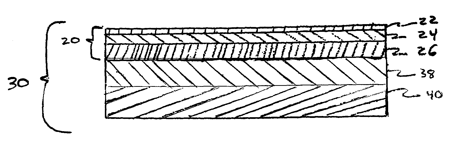
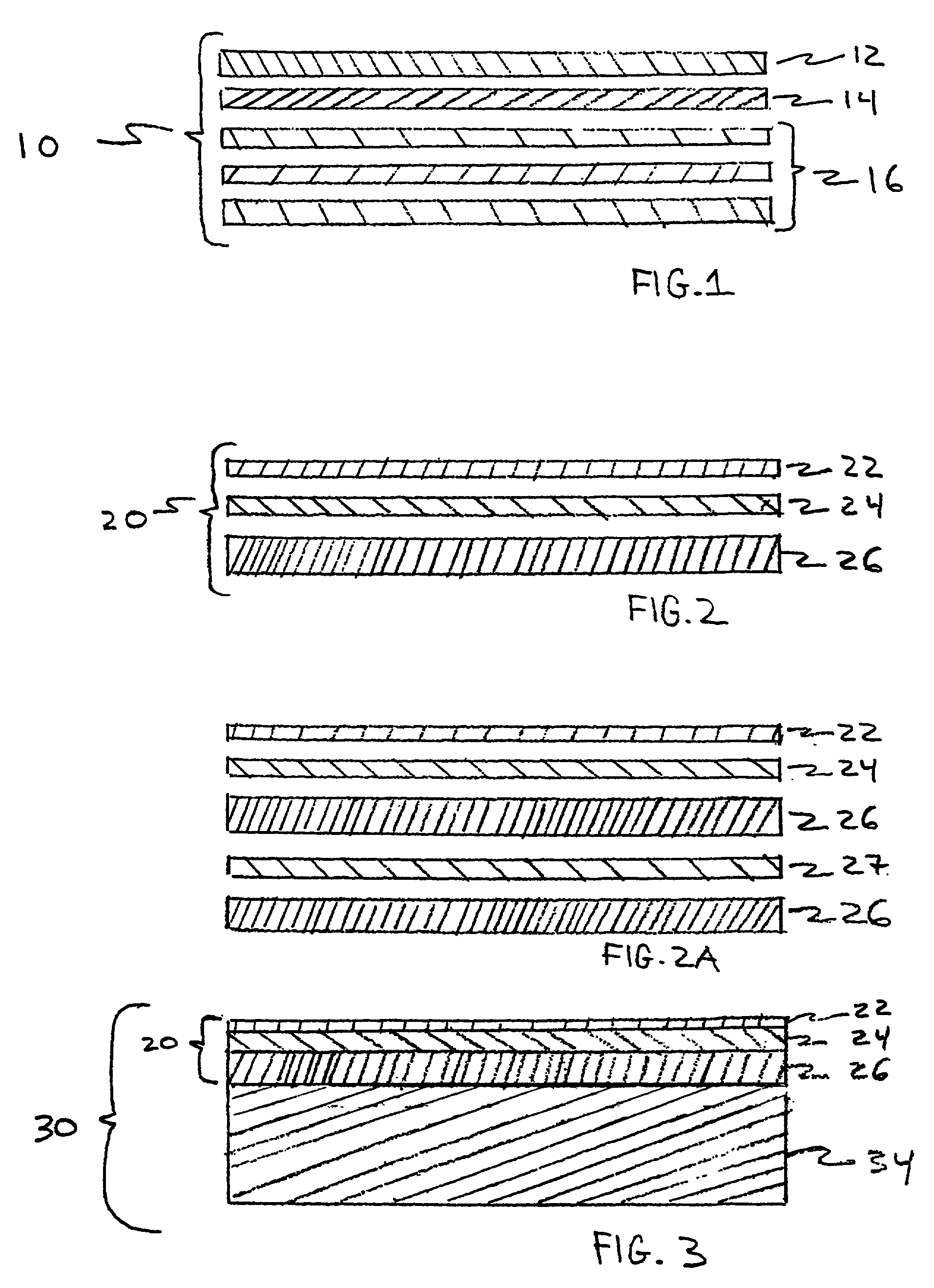
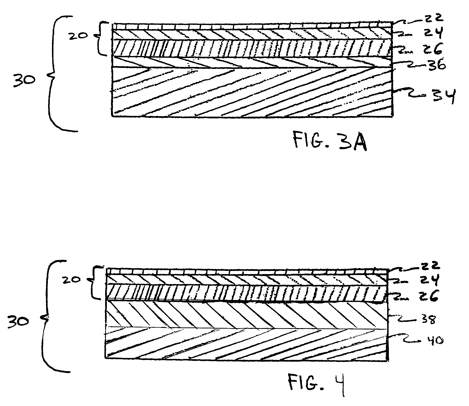
[0081]The Mead abrasive loaded high wear overlay treated with the preferred plasticized melamine resin blend detailed and used in the previous Example 1, corresponding to that used for Sample 4 of Table III, was also used for all the decorative laminate assemblies prepared in this present Example 2. The print papers were either treated with the neat dicyandiamide modified melamine (MF) resin, corresponding to Sample 3 of the previous Example 1, or a proprietary melamine-formaldehyde / urea-formaldehyde (MF / UF) resin blend supplied by Duynea Overlays, Inc. of Tacoma, Wash. The Eastman Chemical Company 0.020 inch thick Eastar PETG Copolyester 6763 was used exclusively for all the decorative laminate assemblies of the present example, wherein the plasticized melamine resin treated overlay, treated print deco paper, and PETG core laminate portion were bonded to a filled PVC composite, or alternatively a cement fiberboard, substrate in a single pressing opera...


PUM

PropertyMeasurementUnit
specific pressureaaaaaaaaaa
temperatureaaaaaaaaaa

Abstract

A decorative laminate assembly having a decorative laminate top layer assembly. This top layer assembly includes, in descending superimposed relationship, a decorative layer and a core layer that includes PETG, or other polymeric material. Preferably, the top layer assembly also includes a wear resistant overlay layer on top of the decorative layer, and the core layer's PETG is in a sheet form. The top layer assembly may be directly bonded to a water resistant substrate. The decorative laminate assembly of the present invention can be used for a variety of purposes, including flooring applications. When the present invention is used for flooring applications, it is preferred that the overlay layer has enhanced wear resistant qualities and that the water resistant substrate comprise PVC or cement fiberboard.

Description

[0001]This is a continuation-in-part of application Ser. No. 09 / 767,556, filed on Jan. 22, 2001 now U.S. Pat. No. 6,803,110.FIELD OF THE INVENTION[0002]The present invention relates generally to decorative laminate assemblies and methods for producing the same, and more specifically, decorative laminate assemblies with enhanced moisture resistance and dimensional stability, which qualities are particularly useful in flooring applications where there will be repeated or prolonged exposure to moisture or water.BACKGROUND OF THE INVENTION[0003]Decorative laminates have been used as a surfacing material for many years, in both commercial and residential applications, where pleasing aesthetic effects in conjunction with desired functional behavior (such as superior wear, heat and stain resistance, cleanability and cost) are preferred. Typical applications have historically included, while not limited to, furniture, kitchen countertops, table tops, store fixtures, bathroom vanity tops, ca...

Claims


Application Information

Patent Timeline
Patent Type & Authority Patents(United States)
IPC IPC(8): B32B27/00B32B27/36B32B27/40B32B29/02D06N7/04E04F15/10B32B33/00B44C3/02B44C3/12B44C5/04E04F15/02
CPCB32B27/36B44C3/02B44C3/12B44C5/04B44C5/0469B44C5/0476E04F15/02E04F15/10B32B37/00Y10T428/24405B32B2307/554B32B2309/02B32B2309/04B32B2309/12B32B2471/00E04F2290/046Y10T428/24554Y10T442/665Y10T428/31565Y10T442/699Y10T428/31591Y10T442/693Y10T442/674Y10T442/3854Y10T442/675
Inventor LAURENCE, KENNETH JOHNDREES, TERRY PAULO'BRIEN, KEVIN FRANCISFAIRBANKS, BOB
Owner THE DILLER
Why Eureka
Try Eureka