Method of protecting a local area of a component

a local area and component technology, applied in the field of local area protection of components, can solve the problems of degradation and consumption of coatings, thermochemical and physical processing of blades after initial manufacturing, and the structural integrity of the underlying part itself is degraded, so as to achieve greater wear resistance, thermal and chemical resistance, and easy and fast processing

Inactive Publication Date: 2006-08-01
ANSALDO ENERGIA IP UK LTD
View PDF24 Cites 22 Cited by
  • Summary
  • Abstract
  • Description
  • Claims
  • Application Information

AI Technical Summary

Benefits of technology

[0006]It is an object of the present invention to find a cheaper, easier and faster method to provide greater wear, thermal and chemical resistance to a masking material so that it remains in sufficient quantity on parts of a component to protect the covered areas during various thermochemical or physical processes to be carried out. It is another object of the invention to find a method of adequately protecting all holes of a component from being dimensionally affected beyond a desired limit with the thermochemical or physical process carried out on the component. This invention is particularly suited to prevent the changing beyond desired limits of the cooling holes in gas turbine blades and stator vanes with a chemical stripping method designed to remove ex-service coatings.
[0009]According to this invention the polymer masking material, when it contained an appropriate filler, could be filled into the cooling holes only up to the exterior surface of the component and still adequately protect the cooling holes from being affected by thermochemical and physical processes. The filler material is selected from particles or fibres of metal, oxide material such as silica, magnesia, calcia, alumina, zirconia, yttria or a mixture there of, which provided adequate wear and thermal resistance in the range of 10 to 90 vol.-% and in a preferred range of 20–60 vol.-%. A range of filler particle sizes is effective in improving wear resistance and thermal resistance of the masking material. Particle sizes from 1 μm average diameter to over 500 μm diameter are possible. However the average particle size from 10 μm to 150 μm, with a preferred range of 40 to 100 μm showed superior improvements to the thermochemical or mechanical resistance and general handling of the masking material compared to a general size range. Metallic fillers, other oxide fillers or organic materials mixtures are also possible.
[0012]It was found that residual polymer on the outer surface of the component would affect the efficiency of the applied thermochemical or physical process, hence the need to clean the entire surface. Thus, a substance which fluoresces under ultraviolet light was added to the masking material, which allows an inspection to locate any unwanted excess residual masking material. Inspection was performed using ultraviolet lights of the types found in normal Florescent Penetrant Inspection (FPI) booths well known to those skilled in the art. Any excess masking material on the surface of the component was removed by mechanical means in preparation for the stripping process. In one embodiment, this is achieved without interruption of the grit blasting process by integrating the UV light source into the grit blasting cell and equipping the blasting cell with windows of appropriately UV blocking glass or plastic. After removing unwanted residual masking material a re-inspection is carried out using ultraviolet light to locate any further unwanted residual masking material. It may be necessary to reapply masking material to the cooling holes, if some of the protecting masking material had been eroded away by the cleaning process of unwanted masking material.
[0014]It was also found that filling the cooling holes or protecting the parts in successive stages which it is at least partially thickened before the application of the next amount in the cooling hole or on the part, and using a gradient of filling materials offered advantages. Only the layers of material at the uppermost portions of the cooling holes required significant volume fractions of solid fillers in the range of 30–80 vol.-% with a grain size of 40–150 μm to a depth not less than 1 mm to give them wear resistance against the grit blasting required to clean the entire outer surface of the component prior to the coating operation.

Problems solved by technology

The demands of operation of the parts in a gas turbine often lead to the degradation and consumption of the coating before the structural integrity of the underlying part itself is degraded.
Thermochemical and physical processing of blades after initial manufacturing can be very problematic for parts with a large number of cooling holes.
However, the holes are already in place during the repair operations, such as acid or alkaline chemical stripping, used to remove old coatings, or grit blasting, water-jet stripping, high speed grinding abrasive techniques and, high speed milling.
Unfortunately, during processing the chemical agents that are applied to remove the coating also react to a certain extent with the base material or the recast zone of laser drilled cooling holes, resulting in dimensional changes—in particular widening of the holes.
Specially shaped cooling holes are particularly susceptible to this as their effectiveness depends heavily on the accuracy of the shape of the hole.
This problem is particularly great for the most modern components which contain hundreds of cooling holes and are designed to operate within very tight tolerance bandwidths—the upper limit on cooling hole diameter to stop the waste of unneeded cooling air which drastically reduces engine efficiency and power output and the lower limit on cooling hole diameter to prevent overheating of the component, which would lead to its premature failure in service.
Chemical etching / stripping methods can lead to an attack of the surface layer of the cooling holes, leaving oversized holes that flow outside of the originally intended specification.
However the wear, thermal and chemical resistance of this material is often insufficient to maintain a desired level of filling in the cooling holes during preparation steps while processing which often involves surface grit blasting to clean the outer surface of the component.
Due to its lack of wear resistance, the plastic or wax readily is eroded away by the grit blasting.
Commonly used plastics are easily infiltrated by the strong acid solutions leading to their spallation and subsequent attack of the no longer protected base material.

Method used


Image

  • Method of protecting a local area of a component
  • Method of protecting a local area of a component
  • Method of protecting a local area of a component

Examples


example 1

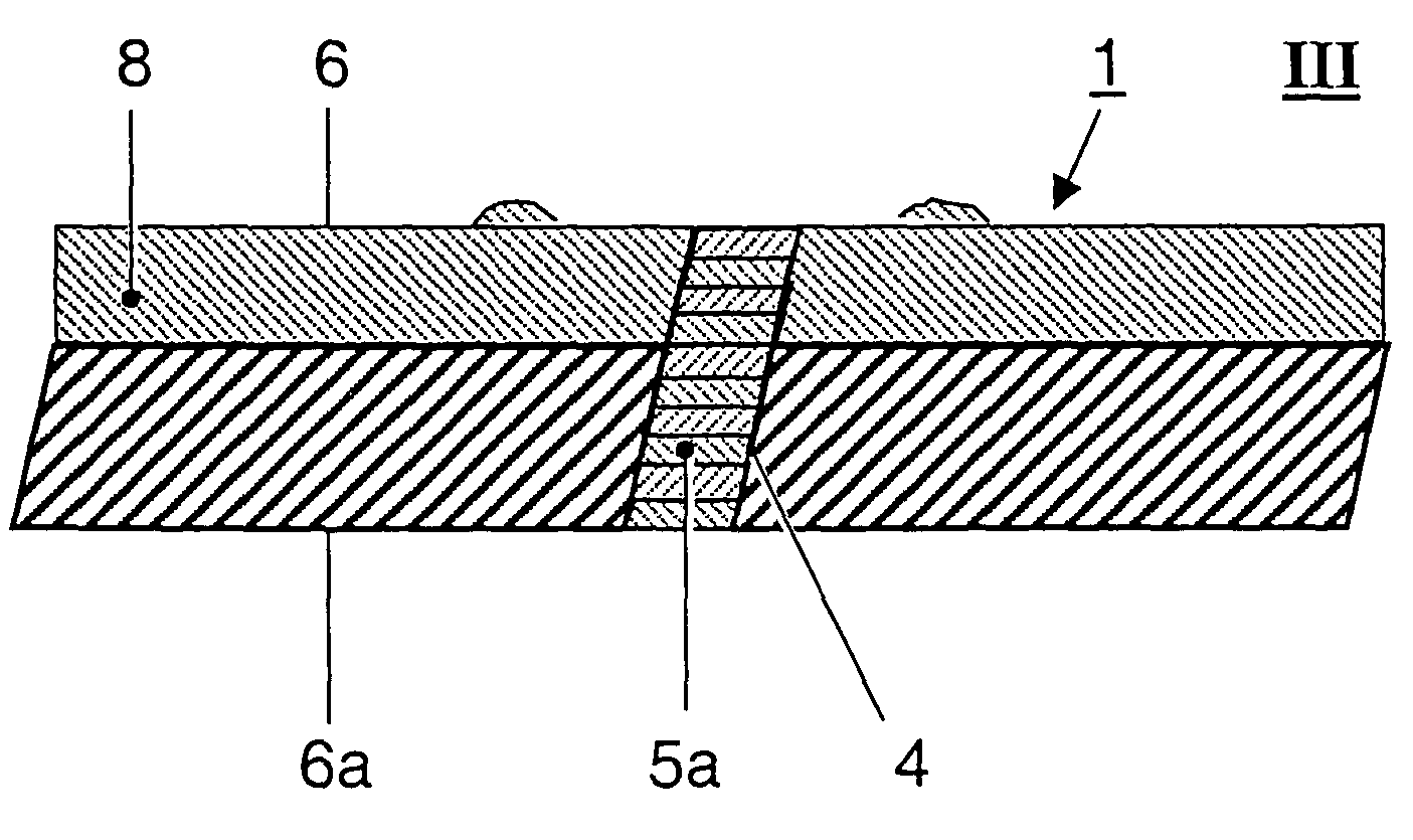
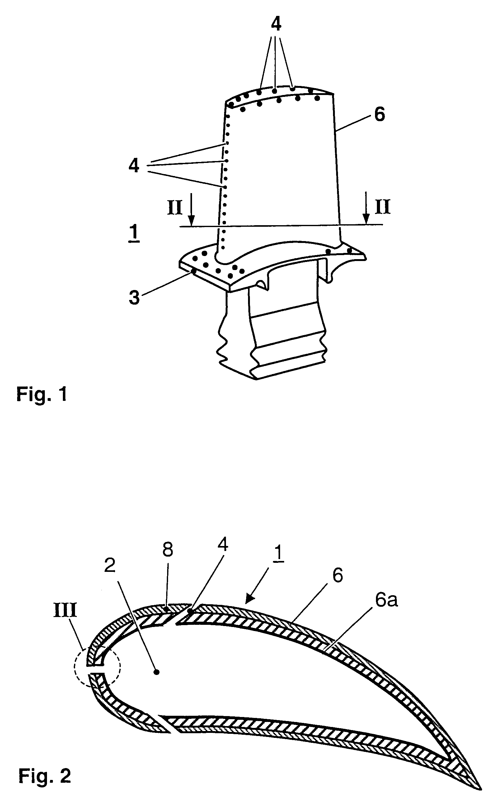
[0046]In the first example, the cooling holes of a coated, gas turbine engine air cooled turbine nozzle article were protected from the influence of the chemically highly reactive baths and mechanical influences occurring during stripping processes of the coating.

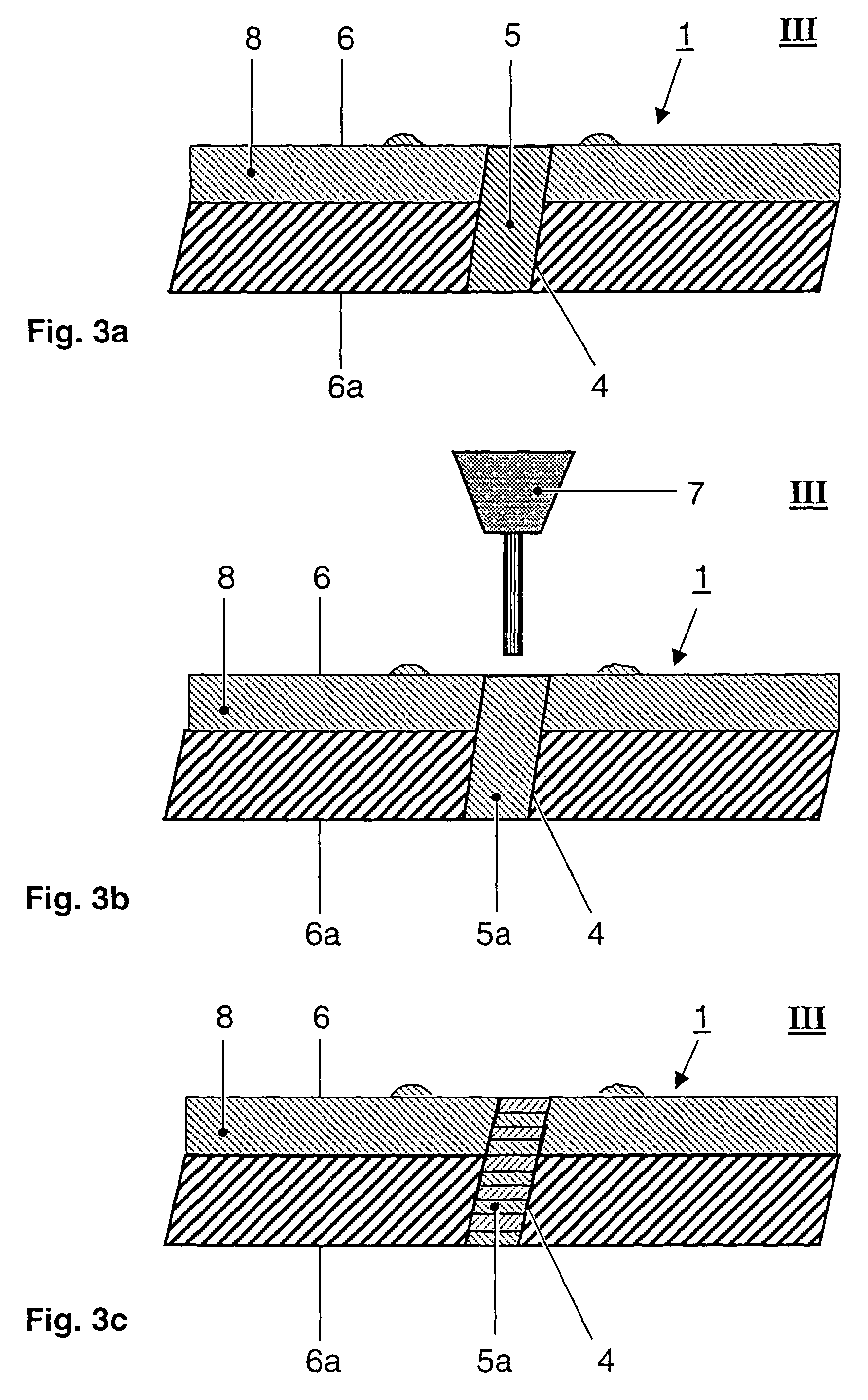
[0047]To fulfil this purpose an appropriate masking substance was prepared by mixing suitable amounts of an adequate inorganic filler material to an UV-polymerizing agent. Thorough and controlled mixing ensured the preparation of a slurry excluding bubble formation and exhibiting the optimum viscosity required for this special kind of application. The blend contained 50% Al2O3-filler with a grain size of 80 μm and 50% resin. The preferential ranges for the constitution of the mixture are 20–60% of Al2O3-filler with a grain size in the range of 40–100 μm and correspondingly 80–40% of polymerizing resin. The blend was subsequently filled into a cartridge of a suitable application system, such as a high precision controlled pn...

example 2

[0048]Another use of the described, mechanically reinforced chemically and thermally highly resistant masking material includes the following steps:

[0049]To fulfil this purpose an appropriate masking substance was prepared by mixing suitable amounts of an adequate inorganic filler material to an UV-polymerizing agent. Thorough and controlled mixing ensured the preparation of a corresponding slurry excluding bubble formation and exhibiting the optimum viscosity required for this special kind of application. The blend contained 60% of Al2O3-filler with a grain size of 100 μm and 40% of resin. The preferential ranges for the constitution of the mixture are 30–75% of Al2O3-filler with a grain size in the range of 50–120 μm and correspondingly 70–25% of polymerizing resin. The blend was subsequently filled into a cartridge of a suited application system such as a high precision controlled pneumatic syringe. The slurry was applied manually onto acid sensitive structures such as brazed joi...


PUM

PropertyMeasurementUnit
grain sizeaaaaaaaaaa
diametersaaaaaaaaaa

Abstract

It is disclosed a method of protecting a local area of components (1) from the effects of thermochemical or mechanical processes carried out on the surface (6) of the component. A masking material (5) containing at least one filler material is applied to the local area so that the local area is protected by the masking material (5). This is at least partially polymerized on the local area. Subsequently the thermochemical or physical processes on the surface (6) of the component (1) are carried out after which the polymerized masking material (5) is removed from the local area of the component (1).

Description

FIELD OF THE INVENTION[0001]The invention relates to a method of protecting a local area of a component from the effects of thermochemical or mechanical processes carried out on the surface of component.BACKGROUND OF THE INVENTION[0002]Components such as gas turbine blades, vanes and other cooled parts often contain cavities that distribute cooling air to a plurality of holes in the wall of the part that lead to the outer surface. Most turbine components are coated for protection from oxidation and / or corrosion with, for example, a metallic coating such as MCrAlY or a diffusion coating and some are also coated with a thermal barrier coating (TBC) for thermal insulation. The demands of operation of the parts in a gas turbine often lead to the degradation and consumption of the coating before the structural integrity of the underlying part itself is degraded. Hence, the metallic and ceramic coating must be removed and reapplied at least once during the lifetime of the component.[0003]...

Claims


Application Information

Patent Timeline
Patent Type & Authority Patents(United States)
IPC IPC(8): B05D1/32B05D1/38B23K26/36C23C4/00F01D5/00F01D5/28
CPCB23K26/367F01D5/28F01D5/00C23C4/005B23K26/364C23C4/01
Inventor STANKOWSKI, ALEXANDERBOEGLI, ANDREASFERNIHOUGH, JOHN
Owner ANSALDO ENERGIA IP UK LTD
Why Eureka
Try Eureka