Silicon-on-insulator active pixel sensors

a silicon-on-insulator and active pixel technology, applied in the field of semiconductor imaging devices, can solve the problems of scaling that can adversely affect the performance of imagers, requires specialized silicon processing that is incompatible with cmos technology, and requires high voltage clocks, so as to reduce the susceptibility to transient effects, reduce the volume of pixels, and increase radiation hardness

Active Publication Date: 2007-01-09
LADARSYST INC
View PDF23 Cites 178 Cited by
  • Summary
  • Abstract
  • Description
  • Claims
  • Application Information

AI Technical Summary

Benefits of technology

[0012]The wafers can be made using different types of silicon and can be made using float zone (FZ) or Czochralski grown silicon, conventional or neutron transmutation doped silicon, or can be formed using epitaxial silicon growth. The insulating layers can be made using materials that facilitate the electrical and optical performance of the sensor, that facilitate wafer manufacturing (for example, through wafer to wafer bonding), or that facilitate semiconductor and sensor processing.
[0031]The first silicon layer is chosen to have a thickness that is selected to enhance or optimize absorption length wherein capacitance and carrier transit time are reduced or minimized. The transit time of photodetectors is a function of the device thickness and the applied bias. Just as increasing the absorption length will increase the optical absorption efficiency, decreasing the thickness of the first silicon layer (charge collection layer) will increase detector bandwidth due to the reduction of carrier transit time. Carriers absorbed outside of the first silicon layer are prevented from drifting or diffusing into the photodetector by the buried oxide layers that contact the first silicon layer. This effect is limited in conventional CMOS sensors, as decreasing the absorption thickness causes the photodetector capacitance between the n and p contacts to increase, resulting in the degradation of the device bandwidth. The first silicon layer doping profiles and thickness can be optimized or otherwise selected during wafer manufacturing and / or during semiconductor manufacturing / device processing. As an example, dopants can be diffused or implanted into the first silicon layer during wafer manufacture so to provide an electric field potential profile or to provide a low impedance contact.

Problems solved by technology

CCDs, however, are high capacitance devices that require high voltage clocks, consume large amounts of power, provide only serial output, and require specialized silicon processing that is incompatible with CMOS technology.
The expected scaling of MOS devices to even smaller geometries will improve the operation and application of CMOS-based integrated circuits, but such scaling can adversely affect the performance of imagers.
Photoelectrons generated within a depletion region are efficiently collected while photoelectrons generated outside the depletion region are collected only inefficiently, and can diffuse into adjacent pixels.
Therefore, CMOS imagers implemented using an unmodified sub-micron CMOS technology generally exhibit a lower quantum efficiency and increased cross-talk compared to imagers implemented with a lower resolution fabrication process.
Increased cross-talk can lead to degraded color performance and smear.
However, the low NA doping is most often incompatible with conventional CMOS processes.
Another problem in imagers made using bulk-CMOS technology is a rise in photodiode leakage current when exposed to radiation.
This rise in leakage current is caused by the use of Local Oxidation of Silicon (LOCOS) processes to create isolation regions.
Although using a radiation-hard fabrication process can reduce leakage currents, such processes are relatively expensive and add to the overall imager cost.
While SOI-MOS devices can provide several advantages over bulk-MOS devices, the thin silicon layer of such devices makes them unsuitable for imagers.
In particular, the SOI silicon layers are too thin to efficiently absorb visible and near-infrared light.
Such devices provide a thick charge collection region, but bulk silicon used for such SOI manufacturing generally is not suited for photodetector manufacture.
Furthermore, bulk silicon is difficult to thin for back-illuminated operation.
Conventional back-thinning processes require a back-surface implant and activation process that typically requires temperatures above 800° C. Thus, these thinning processes are incompatible with standard CMOS metallization processes, and require complex post-processing techniques that are generally difficult to control.

Method used


Image

  • Silicon-on-insulator active pixel sensors
  • Silicon-on-insulator active pixel sensors
  • Silicon-on-insulator active pixel sensors

Examples


Embodiment Construction

[0053]Disclosed below are representative embodiments of methods, apparatus, and systems associated with optical and charged particle sensors. For convenience, these examples are described in a particular sequential order using specific combinations of features. The disclosed methods, apparatus, and systems should not be construed as limiting in any way. Instead, the present disclosure is directed toward all novel and nonobvious features and aspects of the various disclosed embodiments, alone and in various combinations and subcombinations with one another. Further, the disclosed methods, apparatus, and systems are not limited to any specific aspect, feature, or combinations thereof, nor do the disclosed methods, apparatus, or systems require that any one or more specific advantages be present or problems be solved. Method steps are described in a particular order for convenience only, and other orders can generally be used.

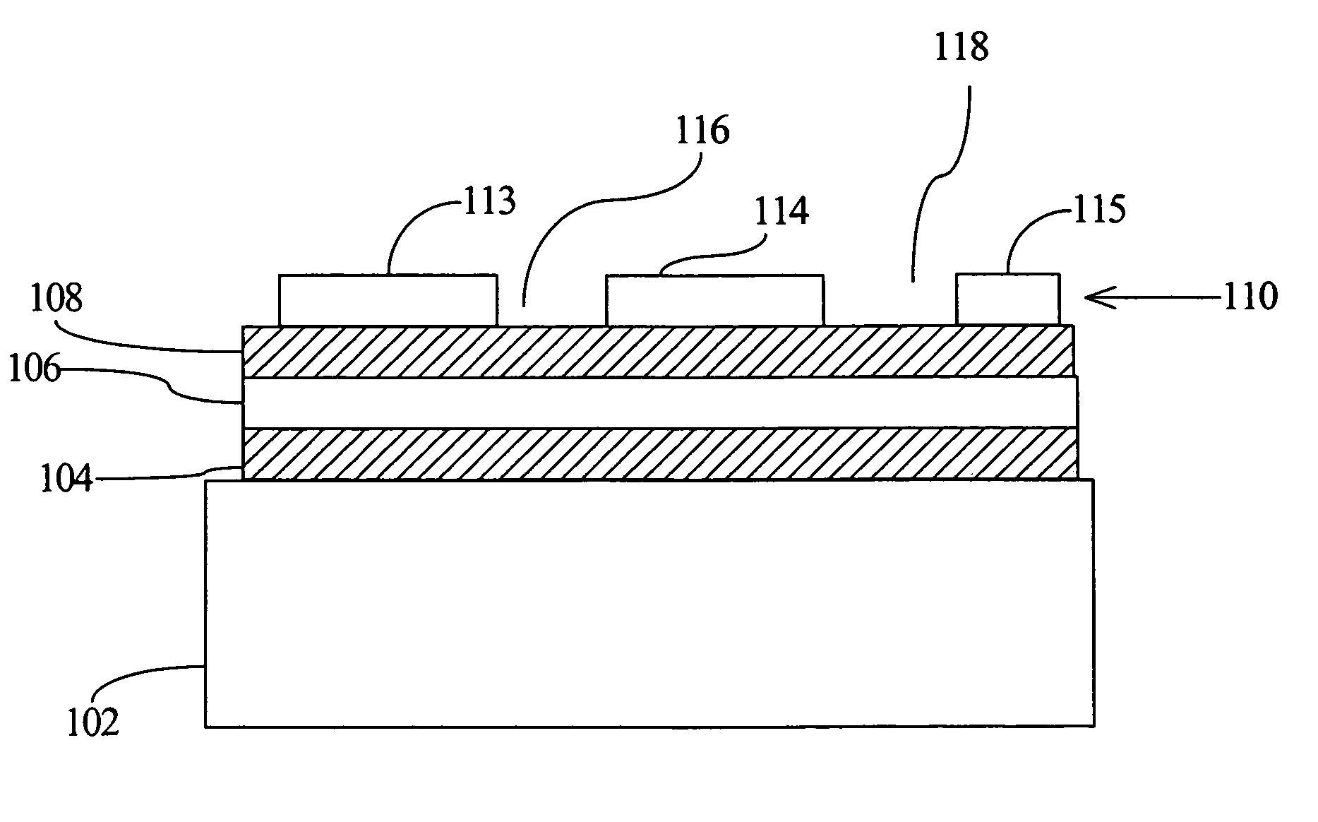
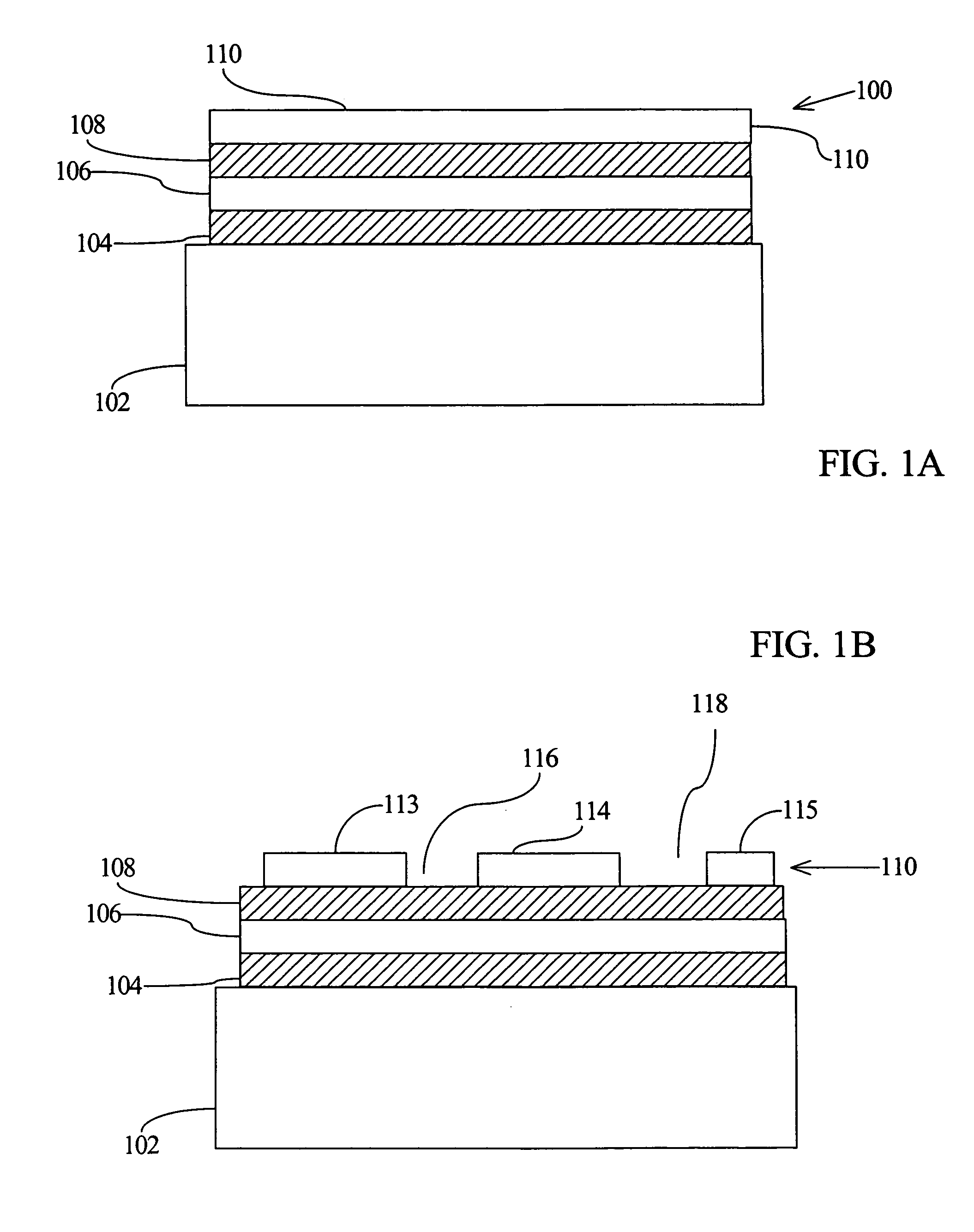
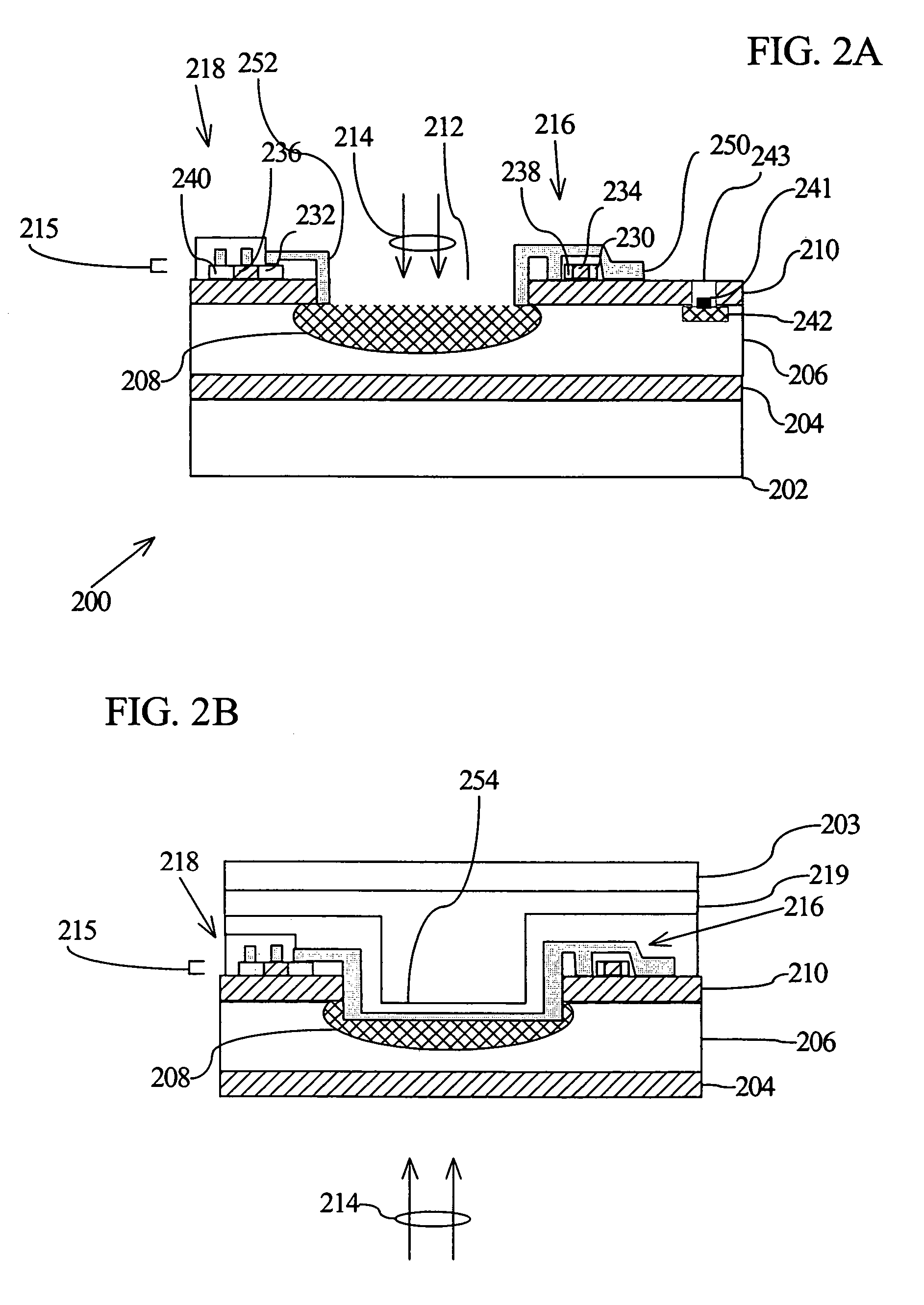
[0054]Sensitive, radiation-tolerant imagers can be fabricate...


PUM


Abstract

Active pixel sensors are defined on double silicon on insulator (SOI) substrates such that a first silicon layer is selected to define radiation detection regions, and a second silicon layer is selected to define readout circuitry. The first and second silicon layers are separated by an insulator layer, typically an oxide layer, and the layers can be independently doped. Doping can be provided in the silicon layers of the SOI substrate during assembly of the SOI substrate, or later during device processing. A semiconductor substrate that supports the first and second layers can be removed for, for example, back side radiation detection, using a second insulator layer (typically an oxide layer) as an etch stop.

Description

RELATED APPLICATIONS[0001]This application claims the benefit of U.S. Provisional Application No. 60 / 521,229, filed Mar. 16, 2004 which is incorporated herein by reference.TECHNICAL FIELD[0002]The disclosure pertains to semiconductor imaging devices and methods of manufacturing such devices.BACKGROUND[0003]Image sensors find applications in a wide variety of fields, including machine vision, robotics, astronomy, navigation, as well as consumer products. While complementary metal-oxide-semiconductor (CMOS) technology has provided the foundation for advances in low-cost, low-power, reliable, highly integrated systems for many consumer applications, charge coupled devices (CCDs) have been, until recently, the primary technology used in electronic imaging applications. CCDs, however, are high capacitance devices that require high voltage clocks, consume large amounts of power, provide only serial output, and require specialized silicon processing that is incompatible with CMOS technolog...

Claims


Application Information

Patent Timeline
Patent Type & Authority Patents(United States)
IPC IPC(8): H01L21/00H01L21/762H01L21/84H01L27/12H01L27/146
CPCH01L21/76254H01L21/84H01L27/1203H01L27/1469H01L27/14634H01L27/14643H01L27/14689H01L27/1463H01L27/14609
Inventor WILLIAMS, JR., GEORGE MELVILLE
Owner LADARSYST INC
Why Eureka
Try Eureka