Devices and methods for reduction of NOx emissions from lean burn engines

a technology of lean burn engine and nox emission reduction, which is applied in the direction of combustion gas production, machines/engines, mechanical equipment, etc., can solve the problems of incompatible lean-burn engine, three-way catalyst technology is not applicable to lean-burn engine, engines or compression ignition engines with very high emissions, etc., and achieves the effect of reducing nox emissions

Active Publication Date: 2007-02-27
INT ENGINE INTPROP CO LLC
View PDF71 Cites 52 Cited by
  • Summary
  • Abstract
  • Description
  • Claims
  • Application Information

AI Technical Summary

Benefits of technology

[0013]The invention provides devices, methods, and compositions for production of reductant from a fuel in an oxygen containing gas stream, and reduction of NOX emissions in an oxygen containing exhaust stream.

Problems solved by technology

Three-way catalyst technology is not applicable to lean burn engines because the large excess of oxygen in the exhaust mixture impedes the reduction of NOX.
This is particularly a problem with diesel engines or compression ignition engines which have very high emissions of NOX and particulate matter (PM).
However, as discussed above, it is incompatible with lean-burn engines due to the excess of oxygen in the exhaust.
This incompatibility is a major limitation of both lean-burn engines and TWC-based emission control technology.
However, one disadvantage of this technology is that it requires a source of NH3 which can be either liquid NH3 stored under high pressure or an aqueous solution of urea which decomposes prior to or on the SCR catalyst to produce ammonia.
In general NH3-SCR technology is limited to large stationary applications, due to its cost and the need for a source of NH3.
Another disadvantage is the need to develop the rather costly infrastructure to supply ammonia or urea to vehicles using this technology.
For these reasons, this technology is not the preferred approach to NOX control on vehicles or very small systems that may be located in populated areas.
Thus, the reduction part of the cycle can be very short, but must be sufficiently long to regenerate a significant fraction of the NOX adsorption capacity.
There are several disadvantages to this technology.
One problem is that converting the exhaust to reducing conditions is difficult to achieve for a lean-burn engine such as a diesel engine designed to run with 8 to 15% O2 in the exhaust stream.
Another problem is that the adsorbent-catalyst components that have been investigated form very stable sulfates, resulting in poisoning of the catalyst by sulfur in the fuel.
Regeneration of the catalyst to remove the sulfur is very difficult and results in degradation of the catalyst performance.
Although H2 and H2 / CO mixtures are good reducing agents for continuous removal of NOX from an O2-containing exhaust stream, present methods for delivering these reducing agents for use in a small mobile system such as a vehicle are cumbersome and / or expensive.
Hydrogen is difficult to store and H2 refueling stations are currently not available.
On-board manufacturing of H2 or H2 / CO mixtures from diesel fuel is possible, but difficult and costly.
A disadvantage with such a device is that it may be difficult to operate for an extended period of time due to formation of coke, which ultimately poisons the catalyst.
Also, this system produces low molecular weight hydrocarbons, which are less effective reducing agents for NOX than H2.
Disadvantages with this system include high energy cost, cost of the system including electronics for the plasma generator and durability issues.
This would require separate tanks, supply system and complexity.
However, this system may be difficult to implement and too complex for NOX removal in mobile systems such as a vehicle.
However, such a system is difficult to scale down.
In addition, these processes that convert the liquid hydrocarbon fuel to H2 and CO in a separate reactor system can have a long start up time, from 1 to 30 minutes.
This would result in a long period of time during which no reducing agent is available for NOx reduction and vehicle NOx emissions levels would remain unacceptably high.
However, the disadvantage of continuous fuel addition is that the high level of O2 in the exhaust stream results in a very high temperature at a fuel-to-oxygen ratio that is good for reforming the fuel to H2 and CO.
However, addition of steam is not desirable because this water must be carried on the vehicle as a feed for the fuel processing system and the water would have to be very pure since typical impurities in tap water such as sodium, calcium, magnesium etc. are poisons for most reforming catalyst materials.

Method used


Image

  • Devices and methods for reduction of NOx emissions from lean burn engines
  • Devices and methods for reduction of NOx emissions from lean burn engines
  • Devices and methods for reduction of NOx emissions from lean burn engines

Examples


example 1

Catalyst Preparation

[0130]A monolithic structure was prepared as described in U.S. Pat. 5,259,754.

[0131]Palladium nitrate was diluted in deionized water at a concentration of about 0.18 g Pd / ml and then zirconium oxide powder having a surface area of about 75 m2 / g was added with stirring. The mixture was then evaporated to dryness and the resulting powder calcined in air at 700° C. for 10 hours. The final palladium concentration in the final catalyst powder was 5.5% by weight. The Pd / ZrO2 catalyst was slurried with water and 10% by weight of a 20% zirconium acetate solution to form a slurry of about 30% solids. The Pd concentration in the solid oxide was 5%.

[0132]Rhodium trichloride was dissolved in deionized water at a concentration of about 0.04 g Rh / ml and then zirconium oxide powder with a surface area of about 75 m2 / g was added with stirring. While stirring the mixture, a solution of 20% ammonium hydroxide in water was added to a pH of 8. the mixture was then evaporated to dryn...

example 2

Catalytic Conversion of Fuel Injected at Varying Frequencies to H2

[0134]The catalyst from Example 1 was placed in a flow reactor containing a gas supply and mass flowmeters for air, N2 and He as a mass spectrometer quantitative tracer, an electric heater, an air assist sprayer for water, and a pressurized fuel sprayer for diesel fuel injection (Mitsubishi MR560553). The catalyst was located in a 50 mm diameter insulated section with thermocouple temperature sensors upstream and downstream of the catalyst. A sampling probe for a mass spectrometer was located about 50 cm downstream of the catalyst outlet.

[0135]The flow of air, nitrogen, and water was adjusted to a total gas flow rate of 600 SLPM, forming a final composition of 5% H2O, 7% O2 , 0.3% He, and the balance N2. This mixture was then heated to 270° C. using the electric heater. Diesel fuel was injected in pulses of varying frequency, as shown in FIG. 6. The mass spectrometer sampling rate was 2 Hz, and the injection frequenc...

example 3

Effect of Mixing to Provide a Continuous Stream of H2 and CO

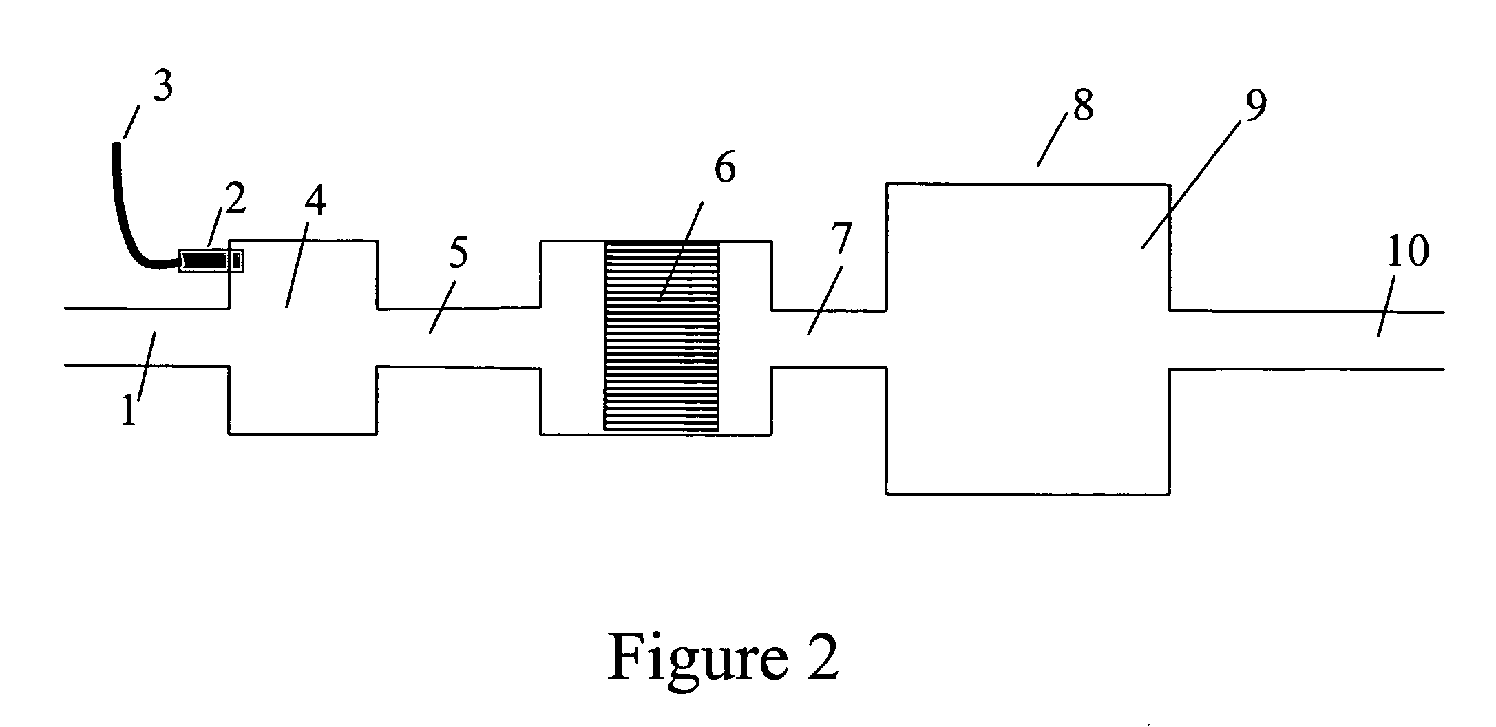
[0136]An experiment similar to Example 2 was performed, but using 22 g catalyst with an 8 mm channel foil height, at a flow rate of 350 SLPM. Fuel pulses were at 0.5 Hz. After exiting the fuel processor catalyst, the resulting gas stream then entered a 38 liter stainless steel mixing chamber, to mix the resulting products. A mass spectrometer was used to follow the composition of the gas stream just downstream of the fuel processor, equivalent to location 7 in FIG. 2 and just downstream of the mixing volume, equivalent to location 10 in FIG. 2. The H2 concentration just downstream of the fuel processor is shown in FIG. 7A and the H2 concentration downstream of the mixing volume is shown in FIG. 7B. These data show that such a mixing volume is sufficient to mix out the pulsing H2 and provide a stream of gas with a relatively constant level of H2. It should be noted that CO was not monitored in these tests but the CO concentr...


PUM


Abstract

The invention provides devices and methods for generating H2 and CO in an O2 containing gas stream. The invention also provides devices and methods for removal of NOX from an O2 containing gas stream, particularly the oxygen-rich exhaust stream from a lean-burning engine, such as a diesel engine. The invention includes a fuel processor that efficiently converts added hydrocarbon fuel to a reducing mixture of H2 and CO. The added fuel may be a portion of the onboard fuel on a vehicle. The H2 and CO are incorporated into the exhaust stream and reacted over a selective lean NOX catalyst to convert NOX to N2. thereby providing an efficient means of NOX emission control.

Description

CROSS REFERENCE TO RELATED APPLICATIONS[0001]This application claims the benefit of U.S. Provisional Application 60 / 426,604, filed on Nov. 15, 2002.FIELD OF THE INVENTION[0002]This invention relates to reduction of NOX emissions from a combustion process. The invention also relates to removal of NOX from the exhaust from an internal combustion engine, particularly a lean burn internal combustion engine, such as a diesel engine. The invention also relates to fuel processing, whereby a hydrocarbon fuel is converted into a reducing gas mixture containing H2 and CO, and use of the H2 and CO to reduce NOX in an oxygen-rich exhaust stream.BACKGROUND OF THE INVENTION[0003]Emissions regulations are continually being tightened to improve air quality in many locations around the world. Over the past 30 years, the regulations relating to spark ignited engines have been tightened and the allowable emissions substantially reduced. These engines operate at or near a stoichiometric air / fuel ratio ...

Claims


Application Information

Patent Timeline
Patent Type & Authority Patents(United States)
IPC IPC(8): F01N3/00F01N3/08F01N3/20F01N13/02
CPCF01N3/0814F01N3/0842F01N3/0871F01N3/2053F01N3/2066F01N13/009F01N13/0093F01N2240/30F01N2610/03F01N2610/04Y02T10/24F01N2240/20Y02T10/12Y02A50/20
Inventor DALLA BETTA, RALPH A.CIZERON, JOELSHERIDAN, DAVID R.
Owner INT ENGINE INTPROP CO LLC
Why Eureka
Try Eureka