
DNA joining method

a dna and plasmid technology, applied in the field of recombinant dna technology, can solve the problems of difficult determination, loss of sequences within the pcr-amplified region, and notoriously poor cutters

Inactive Publication Date: 2009-08-18
UNIVERSITY OF GUELPH
View PDF9 Cites 35 Cited by
  • Summary
  • Abstract
  • Description
  • Claims
  • Application Information

AI Technical Summary

Benefits of technology

[0063]The present invention provides a method to directionally clone any template DNA molecule into a single restriction site of any vector. The vector ends may be generated from any r

Problems solved by technology

One problem often encountered with this method is that REs are notoriously poor cutters when their recognition sequences are close to the ends of the DNA substrate (Kaufman and Evans 1990).
A second complication is that sequences within the PCR-amplified region can be lost if a second restriction site for the same RE is unknowingly present.
It should be noted that during any ligation reaction, it is critical that the vector and insert are present in appropriate ratios, which is often difficult to determine.
Blunt-end cloning of PCR fragments has also been used extensively, although this technique is relatively inefficient because of the problems encountered by DNA ligase when joining together two blunt-ended DNA molecules.
This technique is also complicated by the fact that Taq polymerase (the prototypical PCR amplifying enzyme) has a propensity for adding 3′ terminal adenine residues through its terminal transferase activity (Clark 1988; Mole, Iggo et al.
In addition to the problems produced by the amplifying polymerase, this technique does not allow for directional cloning, meaning that the orientation of insert in the recombinant DNA cannot be predetermined.
The most significant drawback of this technique is that vectors must be specifically engineered to produce compatible ends.
The main limitation to these methods is that a vector supplied by the manufacturer must be used and a second subcloning step is often necessary to move the cloned DNA fragment into a vector of choice.
Such vectors, however, required extensive manipulations to create.
Some other potential problems with these kits have been reported recently (Hengen 1995).
High backgrounds were observed for the pCR-Script vector when tested alone, PCRII contains a pBR322 origin of replication and thus replicate to low copy numbers, and repeated freeze-thaw cycles at −20° C. can lead to instability and loss of the T-tails.
All the T-vector techniques suffer from the drawback that they are non-directional and require a ligation step.
Another limitation of this technique, is that the TOPO recognition sequence must be located within 10 bp from the 3′-ends of the vector, and furthermore, the insert must have a 5-OH group.
The issue has been raised that internal recognition sequences within the amplified DNA may result in complications, however these sites are simply religated and do not impose any restrictions on this technique (Shuman 1994; Stivers, Shuman et al.
Under general use, the Invitrogen kit provided another potential problem (unpublished results).
The traditional method for screening clones, called blue-white selection, does not produce definitive results with the Invitrogen kit.
The researchers must therefore use Taq polymerase which has a significantly increased error frequency.
One drawback of this method is the requirement for a modified base (deoxyuridine) in the primer, and success relies on two enzymes in addition to ligase treatment.
A second more obscure variation of UDG-cloning involves the use of a non-base residue called 1,3-propanediol in a predetermined position within the PCR primer, which can yield compatible 5′-ends for cloning, however, this method is much less efficient than other ligase-independent cloning methods (Kaluz and Flint 1994).
This process involves two distinct PCR amplifications, thus increasing the probability of introducing PCR errors into the products.
This technique may not be suitable for use with traditional E. coli strains because independent reports indicate that DH5α cells cannot catalyze intramolecular gap repair, and thus might not be expected to catalyze inter-molecular recombination (Hanahan, 1985).
These techniques require delicate control of incubation periods, as these enzymes are extremely efficient, and if one is not careful, excess DNA can be digested.
A second drawback to these specific methods is the requirement for the addition of dTTPs or dATPs in the exo reaction to stop the enzyme at the appropriate positions.
Its limitation is that only blunt-ended or 5′-overhanging substrates can be efficiently cloned.

Method used


Image

  • DNA joining method
  • DNA joining method
  • DNA joining method

Examples


experimental examples

Materials and Methods

[0143]Linear substrates were prepared by restriction enzyme digestion of plasmid pDW101, followed by phenol extraction and ethanol precipitation. pDW101 derives from pBluescript (KS+) (Stratagene) through a spontaneous deletion of nucleotides 618, 619 and 621. In some experiments, the linear substrates were purified by agarose electrophoresis and extracted from the agarose using a Geneclean II kit (New England Biolabs). [α−32P] dCTP and [γ−32P] dATP were purchased from NEN / Mandel Scientific. End labeled substrates were generated by treatment with shrimp alkaline phosphatase (United States Biochemical, Cleveland), followed by incubation with either T4 polynucleotide kinase and [γ−32P] dATP (3000 Ci / mmol) or Klenow enzyme and [α−32P] dCTP (3000 Ci / mmol). Unincorporated radionucleotides were removed by G-25 spin columns (Pharmacia) and radioactivity was quantitated by Cherenkov (Schneider, 1971). HindIII-digested lambda phage DNA and HaeIII-digested ΦX174 DNA marke...

experiment 1

Vaccinia DNA Polymerase Purification

[0145]Purification of vaccinia DNA polymerase from vaccinia-infected BSC-40 cells has been described (McDonald and Traktman 1994; Willer, Mann et al. 1999). Briefly, a crude lysate from 60 150-cm2 dishes of BSC40 cells co-infected with vTMPOL and VTF7. was subjected to purification through DEAE cellulose, phosphocellulose, ceramic hydroxyapatite and HiTrap heparin columns. Active fractions eluting at each chromatographic step were determined by DNA polymerase assays (Willer, Mann et al. 1999). Protein purity was determined by silver staining of denaturing polyacrylamide gels. Protein concentrations were assayed by using a dye-binding assay (Biorad) and a bovine serum albumin standard.

experiment 2

Assay for Correct DNA Polymerase Activity

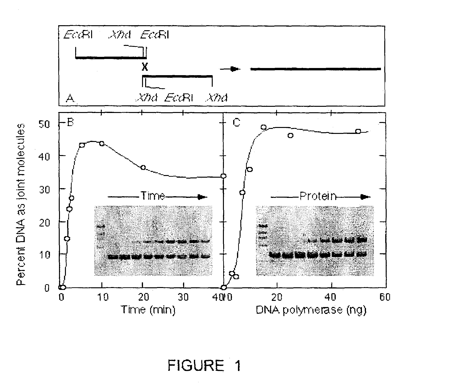
[0146]We measure the intrinsic strand joining activity of DNA polymerases, such as those encoded by bacteriophage (e.g. T4, T7), bacteria (e.g. E. coli), fungi (e.g. S. cerevisiae) and viruses (e.g. poxviruses, herpes viruses, adenoviruses, African swine fever virus and other Iridoviruses, and Bacculoviruses). The polymerases are assayed to measure their activity in the DNA joining reaction by incubating a reaction mixture comprising 30 mM Tris-HCl (pH 7.9 ), 5 mM MgCl2, 70 mM NaCl, 1.8 mM dithiothreitol, 88 μg / mL acetylated BSA, 350 ng of each of a first and second linear DNA substrate and the polymerase to be assayed. The first and second linear DNA substrate must have complementary nucleotide sequences on their right and left ends respectively and may be obtained by a variety of methods including chemical synthesis and derivation of nucleic acid fragments from native nucleic acid sequences existing as genes, or parts of genes, in a genome,...


PUM

PropertyMeasurementUnit
Temperatureaaaaaaaaaa

Abstract

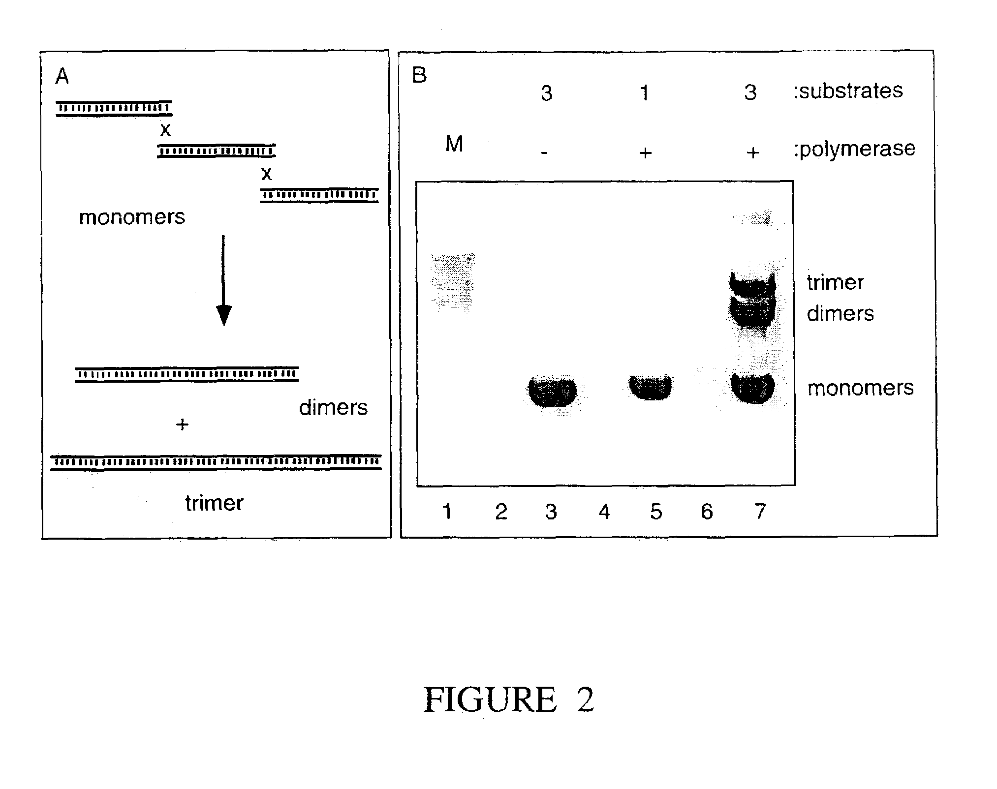
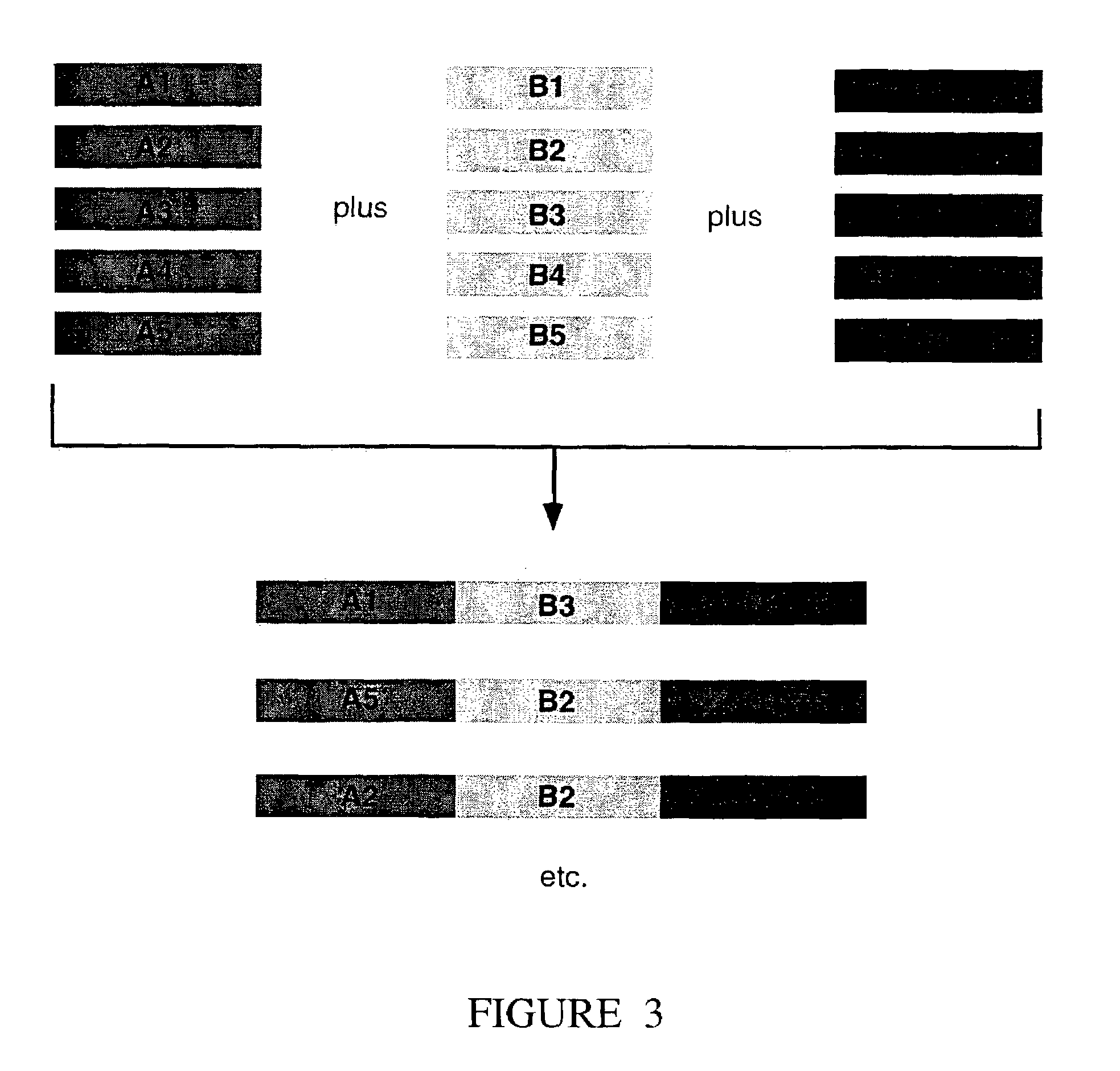
The present invention provides a method to directionally clone any linear template DNA molecule into any linearized vector. The vector ends may be generated from any restriction enzyme cleavage. The method does not require a ligation step nor the use of carefully controlled conditions as is required with methods involving specific exonucleases alone. It has been determined that specific DNA polymerases are able to efficiently join one or more linear DNA molecules sharing ends with appropriate complementation.

Description

RELATED RELATIONS[0001]This application is the national phase entry of PCT / CA01 / 00283 filed Mar. 7, 2001 and claims priority from U.S. Provisional Patent Application No. 60 / 187,401 filed Mar. 7, 2000, Canadian Patent Application No. 2,317,865 filed Sep. 1, 2000 and U.S. Provisional Patent Application No. 60 / 263,771 filed Jan. 25, 2001.FIELD OF THE INVENTION[0002]The present invention is in the field of recombinant DNA technology. Specifically, the present invention relates to a method of directionally joining one or more DNA molecules using a DNA polymerase, and the application of this method to the cloning of PCR products.BACKGROUND OF THE INVENTION[0003]The Polymerase Chain Reaction (PCR) (Mullis and Faloona 1987; Saiki, Gelfand et al. 1988) is an integral technique in scientific research. Cloning of PCR products is often an obligate step towards reaching a research objective. PCR-cloning presents numerous challenges and various techniques have been devised over the years to minim...

Claims


Application Information

Patent Timeline
IPC IPC(8): C12Q1/68C07H21/04C12N15/00C12N15/09C12N15/66
CPCC12N15/66
Inventor EVANS, DAVID H.WILLER, DAVID O.YAO, XIAO-DAN
Owner UNIVERSITY OF GUELPH
Learn More