
Low pressure drop, highly active catalyst systems using catalytically active gold

a catalyst and high-active technology, applied in the field of gold-based catalyst systems, can solve the problems of ineffective oxygen transport of carboxyhemoglobin to body cells, carbon monoxide is toxic gas, and co concentrations higher than 1200 ppm are considered immediately dangerous to life and health, and achieve low pressure drop characteristics. , the effect of facilitating attraction

Inactive Publication Date: 2011-06-07
3M INNOVATIVE PROPERTIES CO
View PDF27 Cites 51 Cited by
  • Summary
  • Abstract
  • Description
  • Claims
  • Application Information

AI Technical Summary

Benefits of technology

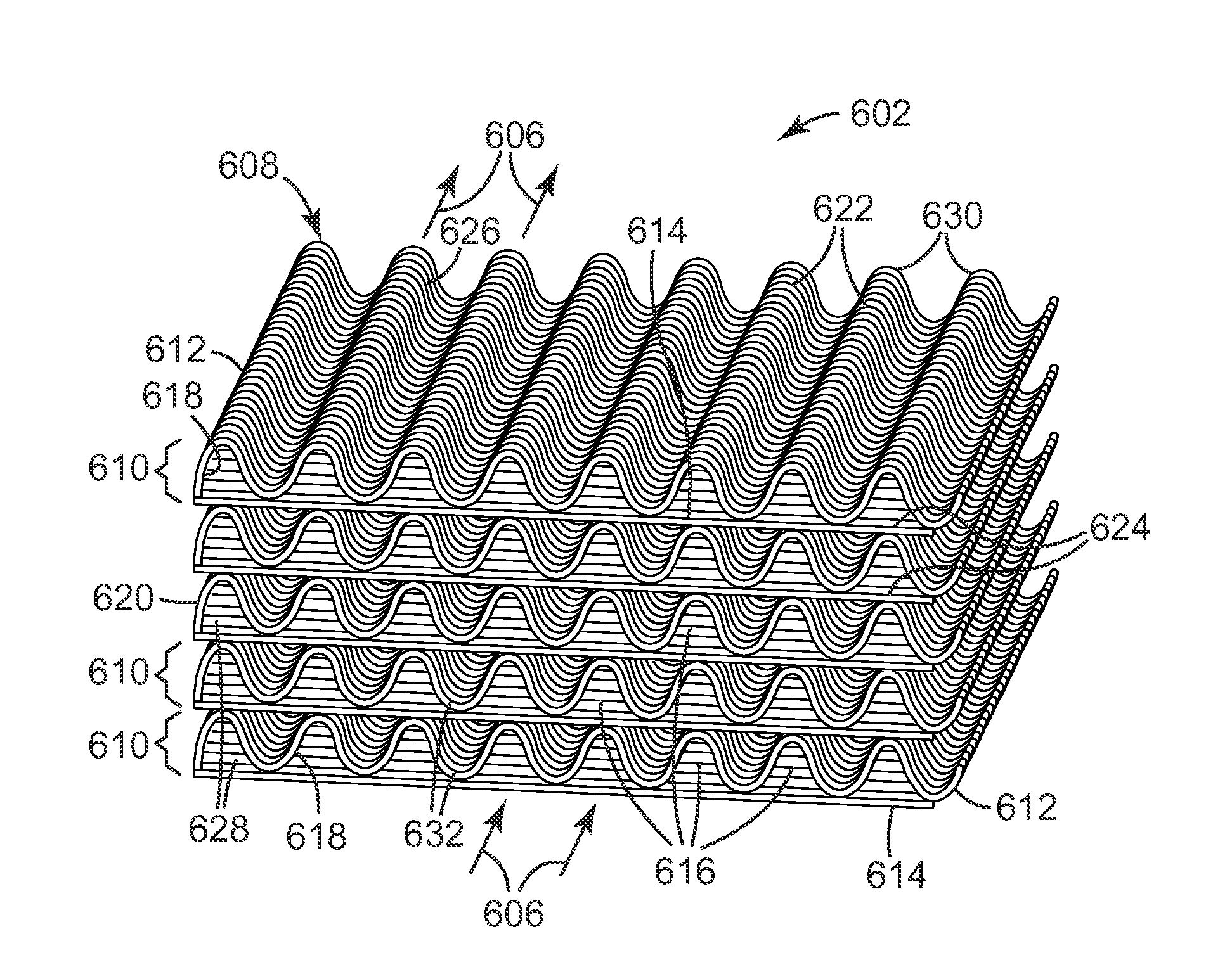
The present invention provides highly active, low pressure drop catalyst systems. These systems have a unique structure that allows the catalyst to be supported on the surface of flow-through channels, which results in a high degree of catalytic activity. The catalyst particles are deposited on the channels in a way that maintains fluidic communication with the fluid stream being treated. The catalyst system can be used in a variety of applications, including CO abatement, catalysts for purification of exhaust gases, and fine chemical synthesis. The catalyst system is open-channeled, which reduces potential for fouling and plugging. The invention also provides a method for selectively oxidizing CO relative to hydrogen, which is useful in hydrogen fuel cell applications.

Problems solved by technology

Carbon monoxide is a toxic gas formed by incomplete burning of organic materials.
Carbon monoxide combines with blood hemoglobin to form carboxyhemoglobin which is ineffective at transporting oxygen to body cells.
CO concentrations higher than 1200 ppm are considered immediately dangerous to life and health by the U.S. National Institute of Occupational Safety and Health (NIOSH).
Poorly operating engines, machinery, heating equipment, ventilation equipment, air conditioning equipment, and other equipment may also output CO, contaminating the air in buildings and vehicles.
These devices tend to be heavy, bulky, expensive and require special training for effective use.
It is not feasible to equip everyone in an area with such devices.
A fire or other sudden unexpected release of carbon monoxide in a building, public place, vehicle, mine, submarine, other marine vessel, or the like may require that individuals quickly escape from an area containing dangerous concentrations of the gas.
Typically, the CO levels encountered are usually less than 200 to 300 ppm, but even these CO levels can cause headaches, dizziness and nausea to drivers and passengers.
In these applications, large volumes of gas and high flow rates can be encountered.
However, the low boiling point and high critical temperature of CO make its removal by physical adsorption very difficult when the CO is present at room temperature.
Conventional gas mask canisters and filters based on activated carbon adsorbents have been relatively useless as a practical matter against high concentrations of carbon monoxide.
However, many CO oxidation catalysts are only active at temperatures of 150° C. or higher.
Hopcalite is a very active catalyst for CO oxidation even at temperatures as low as −20° C. The major disadvantage of hopcalite is that its capability for CO oxidation is quickly destroyed by water vapor in the air.
However, most of these catalysts are only active at temperatures around 150° C.
However, operation at high relative humidity (RH) with low CO inlet concentrations results in capillary condensation of water vapor in the micropores of the catalyst support (usually alumina or silicagel).
This causes slow loss of activity as access to active sites is blocked by condensed water.
A significant disadvantage of these catalysts is the high loading of expensive platinum group metal necessary to meet the requirements for respiratory protection against CO.
Even so, highly active gold catalysts have been difficult to prepare reproducibly.
Scaleup from small lab preparations to larger batches has also proved difficult.
These technical challenges have greatly hindered the industrial application of gold catalysts.
This is unfortunate since the very high activities of gold catalysts for CO oxidation at ambient and sub-ambient temperatures and their tolerance for high water vapor concentrations make them otherwise strong candidates for use in respiratory protection filters and in other applications in which oxidation of CO would be desired.
This tendency to coagulate makes ultrafine gold hard to handle.
Coagulation also is undesirable inasmuch as the catalytic activity of gold tends to fall off as its particle size increases.
These methods, however, suffer from difficulties aptly described by Wolf and Schuth, Applied Catalysis A: General, 2002, 226 (1-2) 1-13 (hereinafter the Wolf et al. article).
The Wolf et al. article states that “[a]lthough rarely expressed in publications, it also is well known that the reproducibility of highly active gold catalysts is typically very low.” The reasons cited for this reproducibility problem with these methods include the difficulty in controlling gold particle size, the poisoning of the catalyst by ions such as Cl, the inability of these methods to control nano-sized gold particle deposition, the loss of active gold in the pores of the substrate, the necessity in some cases of thermal treatments to activate the catalysts, inactivation of certain catalytic sites by thermal treatment, the lack of control of gold oxidation state, and the inhomogeneous nature of the hydrolysis of gold solutions by the addition of a base.
In short, gold offers great potential as a catalyst, but the difficulties involved with handling catalytically active gold have severely restricted the development of commercially feasible, gold-based, catalytic systems.
Thus, this document fails to indicate the importance of using nanoporous media to support catalytically active gold deposited using PVD techniques.
These two documents, however, also fail to appreciate the benefits of using nanoporous media as a support for catalytically active gold deposited via PVD.
However, achieving both low ΔP and increased activity via small particles are in conflict.
Small particles are useless as a practical matter in packed bed configurations due to the resultant high pressure drop through the bed.

Method used


Image

  • Low pressure drop, highly active catalyst systems using catalytically active gold
  • Low pressure drop, highly active catalyst systems using catalytically active gold
  • Low pressure drop, highly active catalyst systems using catalytically active gold

Examples


example 1

Sputtered Au On TiO2 / Kuraray GG Carbon: Effect Of Step Change in CO Inlet Concentration

[0219]This sample was prepared by sputter coating gold onto 300 mL of Kuraray GG 12×20 mesh, activated carbon that had been coated with 10% Ishihara ST-31 titania dispersed in DI water.

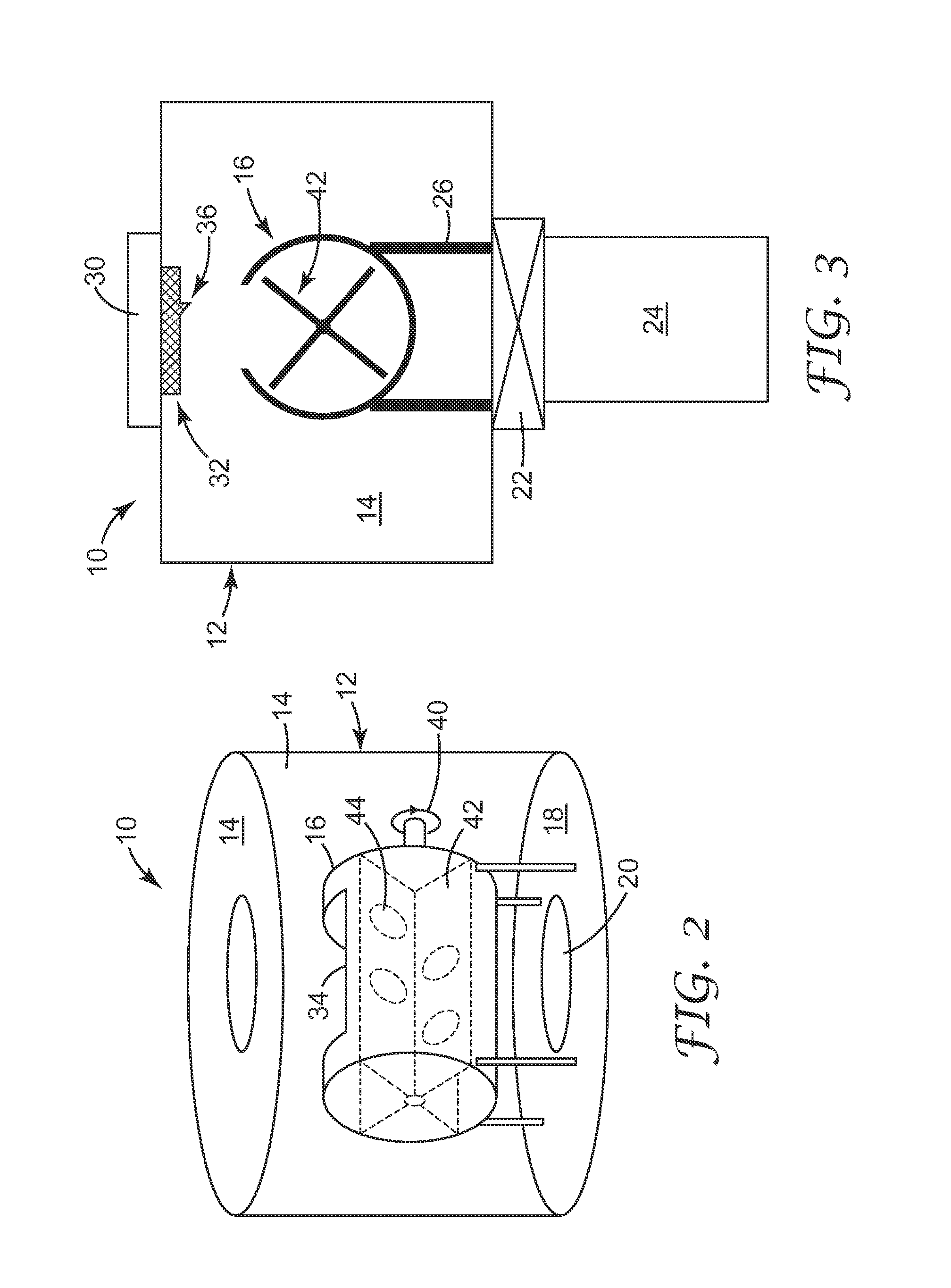
[0220]22.1 grams of ST-31 titania (Ishihara Sangyo Kaisha, LTD, Tokyo, Japan) was dispersed into 160 grams of deionized water utilizing an IKA Ultra Turrax T18 homogenizer (IKA Works, Inc., Wilmington, Del.). The slurry was spritzed (pumping the titania dispersion with a peristaltic pump (Cole Palmer Instruments Co, Chicago, Ill., model wz1r057) at 150 gr / min through a Qorpak finger-actuated trigger-sprayer (Qorpak, Bridgeville, Pa.) as a fine mist) onto 200 grams of Kuraray GG 12×20 mesh activated carbon that was mixed in a 1 gallon steel reactor rotating at 18 rpm at 20 degree angle. After the granules were coated, a heat gun was used to remove enough water to allow the granules to flow freely in the rotating reac...

example 2

Sputtered Au on TiO2 / Kuraray GG Carbon: Lesser Amount of Catalyst Material

[0223]The test of Example 1 was repeated, except only 50 mL of the same catalyst was used. Further, the CO challenge was held at 2500 ppm (no stepwise increase to 10,000 ppm was used in this test). The test results are shown in FIG. 10. The data depicted by the open circles show the temperature data at the outlet, and the data depicted by the black triangles show the detected CO data at the outlet. No CO was detected at the filter outlet during the entire 120 minutes of testing. The temperature of the air at the filter outlet (open circles on the graph) increased slightly and then remained steady at about 42.7° C. This example illustrates the extremely high activity for CO oxidation of the catalysts of the present invention.

example 3

Sputtered Au on TiO2 / Kuraray GG Carbon: Effect of Step Change in CO Inlet Concentration at Higher Flow Rate

[0224]This sample was prepared by sputter coating gold onto 300 mL of Kuraray GG 12×20 activated carbon that had been coated with 10% Hombikat UV100 titania dispersed in DI water. 22.1 grams of Hombikat UV 100 (Sachtleben Chemie Gmbh, Duisburg, Germany) was dispersed into 150 grams of deionized water utilizing an IKA Ultra Turrax T18 homogenizer (IKA Works, Inc., Wilmington, Del.). The slurry was spritzed (pumping the titania dispersion with a peristaltic pump (Cole Palmer Instruments Co, Chicago, Ill., model wz1r057) at 150 gr / min through a Qorpak finger-actuated trigger-sprayer (Qorpak, Bridgeville, Pa.) as a fine mist) onto 200 grams of Kuraray GG 12×20 mesh activated carbon that was mixed in a rotating 1 gallon steel reactor rotating at 18 rpm at 20 degree angle. After the granules were coated, a heat gun was used to remove enough water to allow the granules to flow freely ...


PUM

PropertyMeasurementUnit
sizeaaaaaaaaaa
sizeaaaaaaaaaa
sizeaaaaaaaaaa

Abstract

Highly active, low pressure drop catalyst systems. Catalytically active material is provided on at least a portion of the channel sidewalls of a body comprising one or more flow-through channels. The channel sidewalls preferably bear a charge, e.g., an electrostatic or electret charge, to help adhere the catalytically active material to the sidewall. The catalytically active material preferably includes gold provided on a particulate support, and PVD techniques are used to deposit catalytically active gold onto the support. Optionally, the gold-bearing particulates may be charged as well in a manner to facilitate attraction between the particulates and the sidewalls.

Description

CROSS REFERENCE TO RELATED APPLICATIONS[0001]This application is a national stage filing under 35 U.S.C. 371 of PCT / US2007 / 062970, filed Feb. 28, 2007, which claims priority to U.S. Provisional Application No. 60 / 777,859 filed Feb. 28, 2006, and to U.S. Provisional Application No. 60 / 778,663 filed Mar. 2, 2006, the disclosures of which are incorporated by reference in their entirety herein.PRIORITY CLAIM[0002]The present non-provisional patent application claims priority under 35 USC §119(e) from U.S. Provisional Patent Application having Ser. No. 60 / 777,859, filed on Feb. 28, 2006, by Thomas I. Insley, and titled LOW PRESSURE DROP, HIGHLY ACTIVE CATALYST SYSTEMS USING CATALYTICALLY ACTIVE GOLD, and from U.S. Provisional Patent Application having Ser. No. 60 / 778,663, filed Mar. 2, 2006, by Thomas I. Insley, and titled LOW PRESSURE DROP, HIGHLY ACTIVE CATALYST SYSTEMS USING CATALYTICALLY ACTIVE GOLD, wherein the entireties of said provisional patent applications are each incorporated...

Claims


Application Information

Patent Timeline
Patent Type & Authority Patents(United States)
IPC IPC(8): B01J8/02B01D50/00B01J23/02
CPCB01D53/864B01J35/023B01J21/18B01J23/52B01J23/66B01J35/0013B01J35/0033B01J35/04B01J35/10B01J37/342C01B3/583C23C14/185C23C14/223B01J35/002B01J35/006B01D2257/502B01J37/34C01B2203/044C01B2203/047B01D2255/106B01J35/393B01J35/30B01J35/23B01J35/33B01J35/56B01J35/60B01J35/40
Inventor INSLEY, THOMAS I.BREY, LARRY A.BUCCELLATO, GINA M.FANSLER, DUANE D.JONES, MARVIN E.VEERARAGHAVAN, BADRIWOOD, THOMAS E.
Owner 3M INNOVATIVE PROPERTIES CO
Learn More