Liquid crystal display device and color film plate, and processes for producing the same

a technology of liquid crystal display device and color film plate, which is applied in the direction of liquid surface applicators, coatings, instruments, etc., can solve the problems of corner non-uniformity, corner non-uniformity, and light leakage from the corner portions of wide-screen lcds, and achieves simple and stable process

Inactive Publication Date: 2012-01-10
FUJIFILM CORP
View PDF27 Cites 4 Cited by
  • Summary
  • Abstract
  • Description
  • Claims
  • Application Information

AI Technical Summary

Benefits of technology

[0012]One object of the present invention is to provide a color filter plate comprising a fine-patterned optical anisotropy, and a simple and stable process for producing such color filter plate.
[0013]Another object of the invention is to provide a liquid crystal display device, in which a liquid crystal cell can be optically compensated accurately, having an excellent productivity and improved viewing angle property of color, and a simple and stable process for producing such liquid crystal display device.

Problems solved by technology

Wide-screen LCDs suffer from light leakages from the corner portions, or, in other words, corner non-uniformities.
And, in such a case, the corner non-uniformity may be worsened.
An optical compensation sheet can effectively contribute to reducing the viewing angle dependence of contrast, but cannot contribute to reducing the viewing angle dependence of color sufficiently, and reducing the viewing angle dependence of color is considered as an important problem to be solved for LCD.
For overcoming such problems, it is necessary to optimize wavelength dispersion of birefringence of an optically anisotropic material with respect to each of wavelengths of R, G and B. The LCD is, however, still on the way to thorough improvement in the viewing angle dependence of color, because it is still not easy to control the wavelength dispersion of birefringence of liquid crystal molecules used for ON / OFF display, or for optical compensation sheet.
However, modified polycarbonate film has not been used widely for LCDs yet due to such reasons that, not only the raw material itself is expensive, but also the unevenness in optical properties such as bowing occurs in stretching used in the manufacturing process thereof.
However, in order to pattern a retardation plate in a liquid crystal cell, for example, such troublesome operations are required, in the cell, as formation of an alignment film layer, rubbing treatment, coating, alignment and stabilization of a polymerizable liquid crystal composition, formation, etching treatment of a resist layer, and elimination by peeling of the resist layer.
Consequently, it is difficult to form an optically anisotropic layer having an optically uniform retardation property.
In addition, there is such problem that the retardation of a retardation plate changes before and after the etching due to heat and a solvent of the photo resist that are resulted upon forming the resist pattern.

Method used


Image

  • Liquid crystal display device and color film plate, and processes for producing the same
  • Liquid crystal display device and color film plate, and processes for producing the same
  • Liquid crystal display device and color film plate, and processes for producing the same

Examples


example 1

Method for Preparing Black Photosensitive Composition for Producing Barrier Wall

[0322]A black photosensitive composition K1 was obtained by firstly weighing a K pigment dispersion 1 and propylene glycol monomethyl ether acetate in an amount listed in Table 1, which were mixed at a temperature of 24° C. (±2° C.) to be stirred at 150 RPM for 10 minutes, and then weighing methyl ethyl ketone, a binder 2, hydroquinone monomethyl ether, a DPHA liquid, 2,4-bis(trichloromethyl)-6-[4′-(N,N-diethoxycarbonylmethylami no)-3′-bromophenyl]-s-triazine and a surfactant 1 in an amount listed in Table 1, which were added in this order at a temperature of 25° C. (±2° C.) to be stirred at a temperature of 40° C. (±2° C.) at 150 RPM for 30 minutes. Here, the amount listed in Table 1 is in part by mass, and the detailed composition is as follows.

[0323]

Carbon black (Nipex 35, manufactured by Degussa)13.1%Dispersant (undermentioned compound 1)0.65%Polymer (random copolymer of benzyl methacrylate / methacryl...

example 2

Preparation of Coating Liquid LC-2 for Optically Anisotropic Layer

[0372]A coating liquid LC-2 was prepared in the same manner as the coating liquid LC-R1 used in Example 1, except that a rod-like liquid crystal compound (2) shown below was used in the place of Paliocolor LC242, a polymerization initiator (LC-2-2) shown below was used in the place of the polymerization initiator (LC-1-2), chloroform was used in the place of methylethyl ketone, and neither the chiral agent nor 4,4′-azoxydianisole was used.

[0373]

(Preparation of Optically Anisotropic Layer)

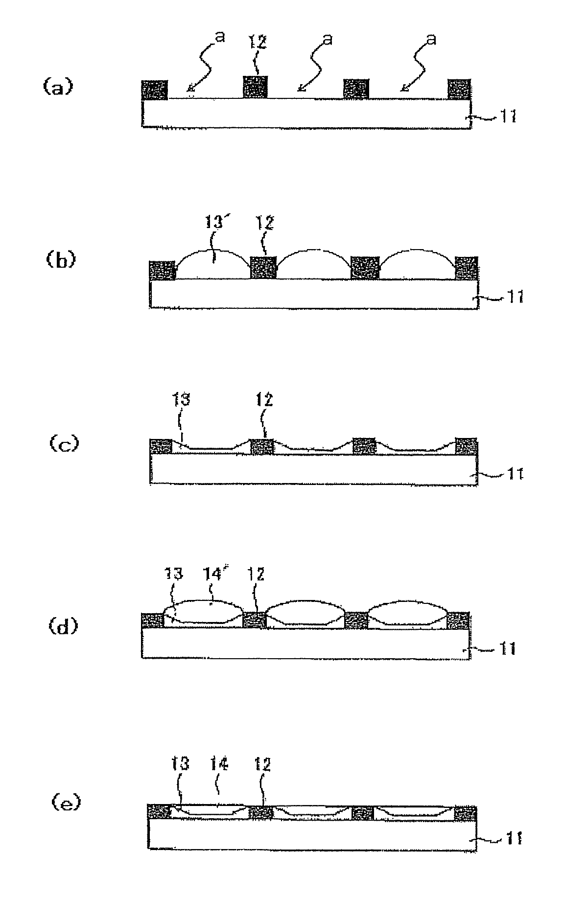
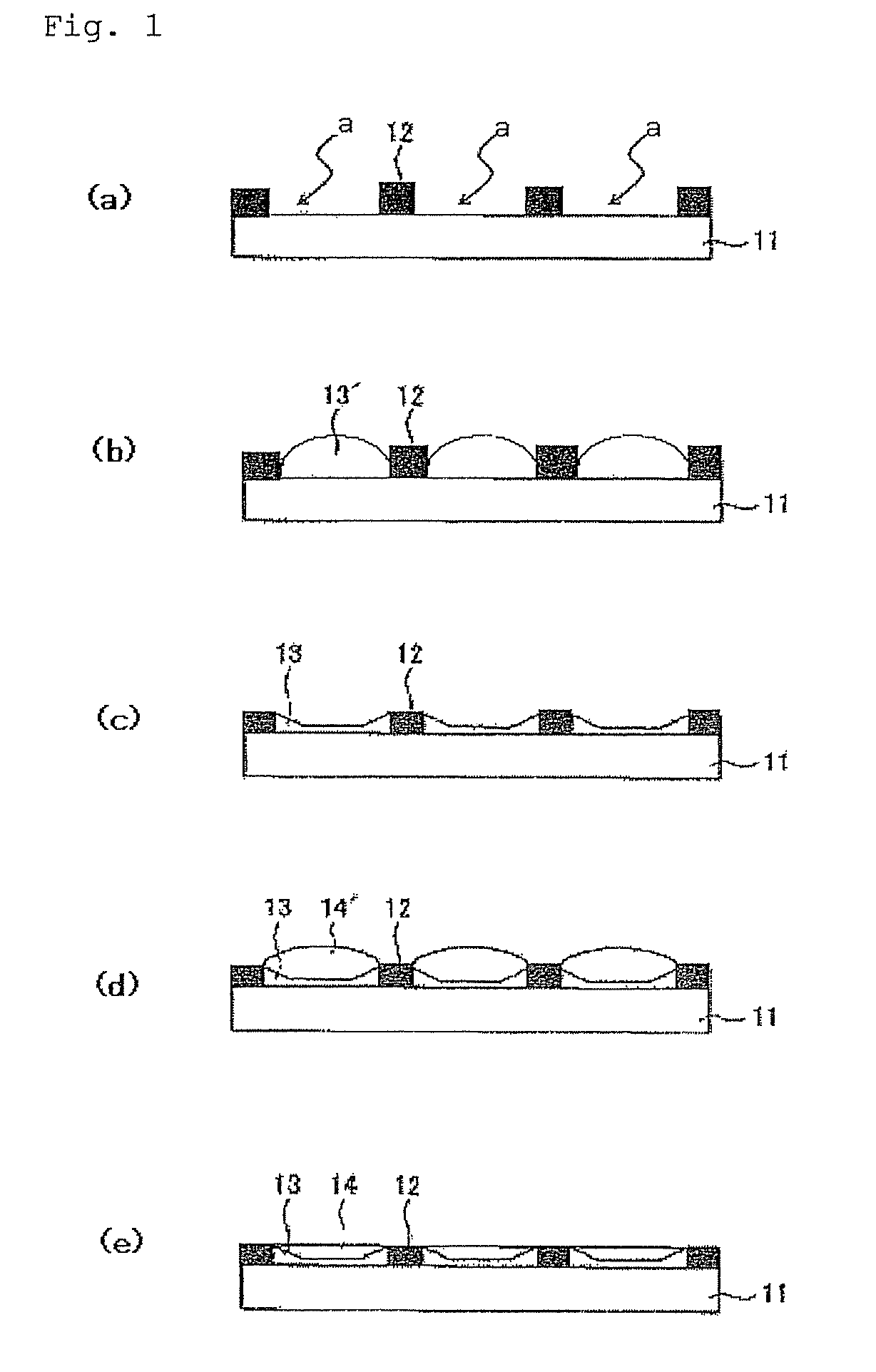
[0374]As optically anisotropic layers for R G and B, layers having a uniform liquid crystal phase were formed, in the similar manner as Examples 1, by ejecting droplets of the coating liquid LC-2 obtained above into concave portions (fine areas) having the alignment layer AL-1 surrounded by the light-shielding barrier wall corresponding R, G and B layer respectively, using a head of piezo system and then heating, drying and aging the ...

example 3

[0381]A VA mode liquid crystal display was produced in the same manner as Example 2, except that optically anisotropic layers R-3, G-3 and B-3 were produced by using a coating liquid LC-3 which was prepared in the same manner as the coating liquid LC-2 except that a rod-like liquid crystal compound shown below was used in the place of the liquid crystal compound (2) shown above. The thicknesses of the optically anisotropic layers R-3, G-3 and B-3 were 1.6 μm, 1,4 μm and 1.1 μm respectively.

[0382]


PUM

PropertyMeasurementUnit
thicknessaaaaaaaaaa
thicknessaaaaaaaaaa
wavelengthaaaaaaaaaa

Abstract

A novel liquid crystal display device is disclosed. The liquid crystal display device comprises a first substrate, a second substrate, liquid crystal held between the first substrate and the second substrate, patterned layers divided into fine areas, disposed on the first substrate, comprising at least a patterned color filter layer and a patterned first optically anisotropic layer laminated in the direction of the normal line of the substrate, and a barrier wall disposed at a boundary portion of the adjacent fine areas of the patterned layers.

Description

BACKGROUND OF THE INVENTION[0001]1. Technical Field of the Invention[0002]The present invention relates to a liquid crystal display device comprising a patterned color filter layer and optically anisotropic layer on a surface such as a liquid crystal cell substrate, and a process for producing the same. The present invention also relates to a color filter plate comprising a patterned color filter layer and optically anisotropic layer, and a process for producing the same.[0003]2. Related Art[0004]A CRT (cathode ray tube) has been mainly employed in various display devices used for office automation (OA) equipment such as a word processor, a notebook-sized personal computer and a personal computer monitor, mobile phone terminal and television set. A liquid crystal display device (LCD) has been more and more widely used instead of a CRT, because it has a thin shape, lightweight and small electric power consumption. A liquid crystal display device comprises, at least, a liquid crystal ...

Claims


Application Information

Patent Timeline
Patent Type & Authority Patents(United States)
IPC IPC(8): G02F1/13363
CPCG02F1/133516G02F1/13363G02F2001/133565G02F2413/02G02F2413/07G02F2413/09G02F1/133565G02F1/133631
Inventor AIKI, YASUHIROMORISHIMA, SHINICHISATO, MORIMASAICHIHASHI, MITSUYOSHI
Owner FUJIFILM CORP
Why Eureka
Try Eureka