
Phosphor and use thereof

a technology of phosphor and phosphor, which is applied in the field of phosphor, can solve the problems of chemical instability, insufficient brightness, and decrease in light brightness of phosphor exposed to such an excitation source over time, and achieve the effect of less reduction of light brightness and higher brightness

Active Publication Date: 2012-06-26
MITSUBISHI CHEM CORP +1
View PDF70 Cites 20 Cited by
  • Summary
  • Abstract
  • Description
  • Claims
  • Application Information

AI Technical Summary

Benefits of technology

The present invention provides a phosphor with higher brightness and longer-lasting light emission compared to existing nitride or oxynitride phosphors. The phosphor has a specific chemical composition that can be adjusted to achieve desired properties such as high design flexibility. The phosphor can be used in various light emitting devices, lighting systems, and displays, providing high efficiency and flexibility in design. The phosphor can be mixed with other phosphors or pigments to achieve desired effects. The phosphor can also be used in a phosphor mixture, which can have different crystal phases and compositions to achieve different light emissions. The phosphor can be excited with ultraviolet light or visible light and has a unique crystal structure that makes it suitable for various applications.

Problems solved by technology

However, the brightness of light emitted from the phosphor exposed to such an excitation source decreases over time.
These phosphors emit red light upon excitation with a visible blue light, but the brightness is insufficient.
In addition, some compositions are chemically unstable, and present problems in terms of durability.
However, the white light emitting device composed of a blue light emitting diode and a yttrium-aluminum-garnet phosphor emits a bluish white light lacking in a red component, so it exhibits unbalanced color rendering.
However, the light emitting devices still have problems to be solved in terms of color rendering.
For example, when the luminescent center of a phosphor shifts to a highly visible green side, color rendering tends to deteriorate but the luminous flux increases.

Method used


Image

  • Phosphor and use thereof
  • Phosphor and use thereof
  • Phosphor and use thereof

Examples


examples

[0307]The present invention is illustrated with reference to the following Examples, but the present invention is not limited to the following Examples without departing from the scope of the invention.

Examples and Comparative Examples of Phosphors Containing Crystal Phase [11]

[0308]The following Examples and Comparative Examples used the raw material powders listed below.

[0309]Silicon nitride (Si3N4) powder, average particle diameter: 0.5 μm, oxygen content: 0.93% by weight, α-type content: 92%

[0310]Aluminum nitride (AlN) powder, specific surface area: 3.3 m2 / g, oxygen content 0.79% by weight

[0311]Calcium nitride (Ca3N2) powder

[0312]Alumina (Al2O3) powder

[0313]Europium nitride (EuN) powder synthesized by nitriding metal europium in ammonia

[0314]Silicon dioxide (SiO2) powder

[0315]Europium oxide (Eu2O3) powder

examples i-1 to i-11

, Comparative Examples I-1 to I-5

[0316]In order to obtain compounds having the theoretical composition formulae listed in Table 4, each of the raw material powders listed in Table 4 was taken at the weight (g) listed in Table 4, and mixed for 10 minutes using a pestle and mortar made of agate. Thereafter, the mixture was filled in a boron nitride crucible (volume filling rate: 38%). All the operations from weighing to mixing the powders were conducted in a glove box capable of keeping a nitrogen atmosphere having a moisture content of 1 ppm or less and an oxygen content of 1 ppm or less.

[0317]The powder mixture was placed in a boron nitride crucible, and mounted on an electric furnace of graphite resistance heating type. The firing operation was conducted as follows: the firing atmosphere was vacuumized by a diffusion pump, the temperature was increased from room temperature to 800° C. at a ratio of 500° C. per hour, nitrogen having a purity of 99.999% by volume was introduced at th...

examples i-12 to i-22

[0331]In Examples I-12 to I-22, Si(3n+2) / 4NnO was used in place of Si2N2O.

[0332]In Examples I-12 to I-22, phosphors expressed by (Eu0.008 / (1−x)Ca(0.008 / (1−x))AlSiN3)1−x(Si(3n+2) / 4NnO)x, wherein n and x differ among the phosphors, were produced and tested in the same manner as Example I-1.

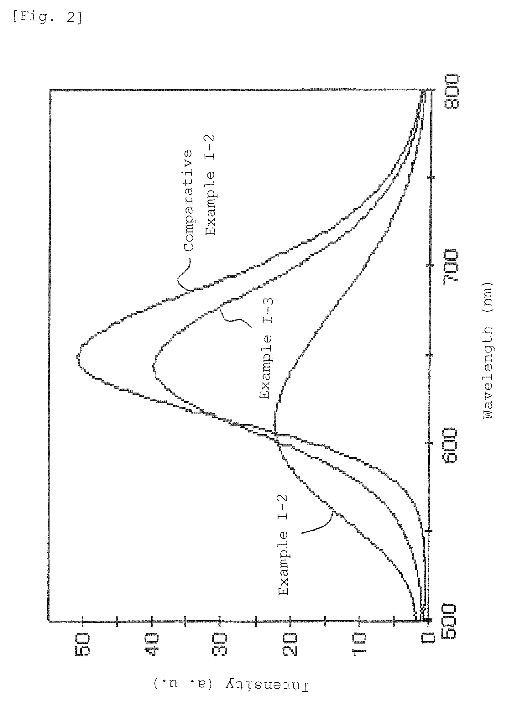
[0333]The thus obtained phosphors were excited with a lamp emitting light having a wavelength of 465 nm, and the emission spectrum was measured using a fluorescence spectrophotometer. Table 6 lists the emission peak wavelengths and the relative brightness determined taking the luminous brightness of the phosphor of Comparative Example I-3 as 100.

[0334]Table 6 also includes the values of Example I-9 and Comparative Examples I-3 and I-5.

[0335]In the phosphors obtained in the above Examples, the alkaline earth metal elements contained in the phosphors are substituted by elements having a lower valence than the alkaline earth metal elements or vacancies, or the rare-earth metal elements contained in the...


PUM

PropertyMeasurementUnit
wavelengthaaaaaaaaaa

Abstract

A phosphor which emits light having high brightness, serves as an excellent orange or red phosphor whose light brightness is less decreased when exposed to an excitation source contains a crystal phase having the chemical composition expressed by the general formula [1]: (1−a−b)(Ln′pMII′1−pMIII′MIV′N3).a(MIV′(3n+2) / 4NnO).b(AMIV′2N3)  [1] wherein Ln′ represents a metal element selected from the group consisting of lanthanoids, Mn, and Ti; MnII′ represents a divalent metal element except the Ln′ element; MIII′ represents a trivalent metal element; MIV′ represents a tetravalent metal element; A represents a metal element selected from the group consisting of Li, Na, and K; 0<p≦̸0.2; 0≦̸a, 0≦̸b, a+b>0, 0≦̸n, and 0.002≦̸(3n+2)a / 4≦̸0.9.

Description

CROSS-REFERENCE TO RELATED APPLICATIONS[0001]This application is a 371 of PCT / JP06 / 310312 filed May 24, 2006 and claims the benefit of JP 2005-151183 filed May 24, 2005, JP 2005-152637 filed May 25, 2005, JP 2005-231870 filed Aug. 10, 2005, and JP 2006-025994 filed Feb. 2, 2006.TECHNICAL FIELD[0002]The present invention relates to a phosphor composed mainly of an inorganic compound, and a lighting system, a display, a phosphor mixture, a phosphor-containing composition, a pigment, and an ultraviolet absorbing agent taking advantage of properties of the phosphor, more specifically a property of emitting fluorescence having a long wavelength of 570 nm or more.BACKGROUND ART[0003]Phosphors are used in fluorescent lamps, vacuum fluorescent displays (VFD), field emission displays (FED), plasma display panels (PDP), cathode ray tubes (CRT), and white light emitting devices. Light emission from a phosphor requires the supply of excitation energy to the phosphor. A phosphor is excited by an...

Claims


Application Information

Patent Timeline
Patent Type & Authority Patents(United States)
IPC IPC(8): C09K11/64H01J5/08H01L33/00H01L33/50
CPCC01B21/0602C01B21/0821C01B21/0823C01B21/0826C04B35/581C04B35/593C04B35/597C04B35/6262C09K11/0883C09K11/7721C09K11/7734C09K11/7792H01L2224/73265C04B2235/3208C04B2235/3217C04B2235/3224C04B2235/3229C04B2235/3418C04B2235/3852C04B2235/386C04B2235/3865C04B2235/3878C04B2235/3895C04B2235/40C04B2235/401C04B2235/402C04B2235/428C04B2235/46C04B2235/5409C04B2235/5445C04B2235/656C04B2235/6562C04B2235/6582C04B2235/761H01L33/502H01L2224/48091H01L2224/48247H01L2924/00014C09K11/77218C09K11/77928C09K11/77348C09K11/55C09K11/77
Inventor HIROSAKI, NAOTOSETO, TAKATOSHIKIJIMA, NAOTO
Owner MITSUBISHI CHEM CORP
Learn More