Multi layer ceramic battery
a ceramic battery and multi-layer technology, applied in the direction of non-aqueous electrolyte cells, cell components, cell component details, etc., can solve the problems of increasing the internal resistance of the battery, limiting performance including power output and energy density, and reducing the efficiency of the battery
- Summary
- Abstract
- Description
- Claims
- Application Information
AI Technical Summary
Benefits of technology
Problems solved by technology
Method used
Image
Examples
example 2
Sponge Sandwich Trilayer Structure with Carbon Anode
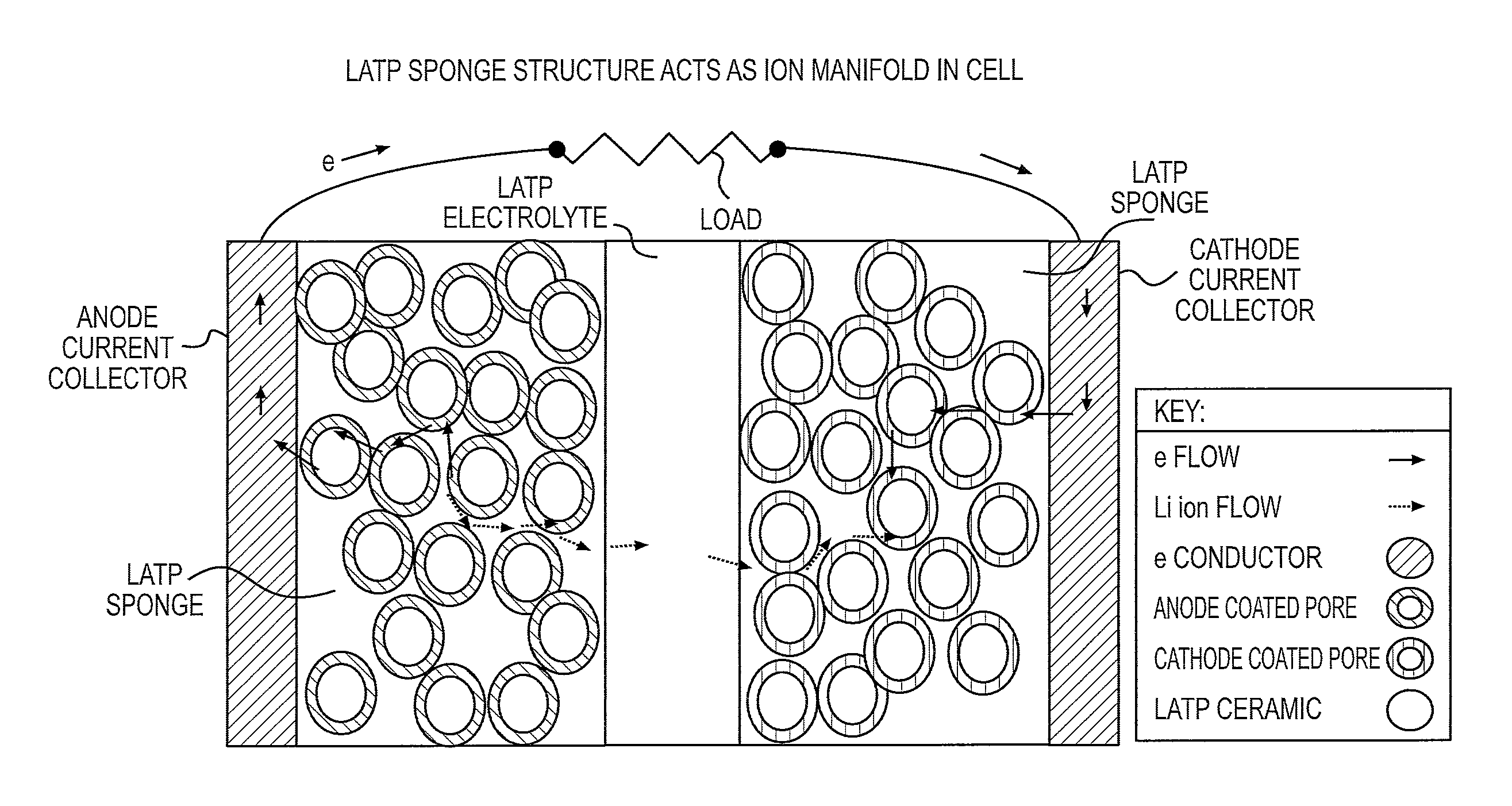
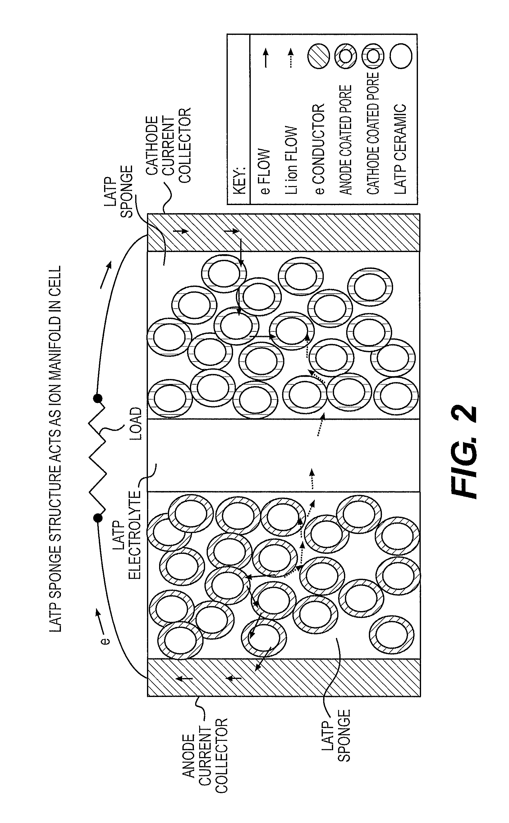
[0040]A porous LATP tape was prepared following the procedure used to make Tape #1 in Example 1. The porous tape (called Tape #4) was prepared in a similar manner as Tape #1 except the formula placed in the ball mill was 22.0 g of LATP material, 0.30 g of DF002 defoamer (from PII), 2.70 g of AD036 modifier (from PII), 8.0 g of acrylic water based binder solution WB40B-53 (from PII) and 27.0 g of Deionized water. The ball mill was rotated to result in milling for 16 hours.
[0041]After 16 hours of milling, the ball mill was opened and 14.7 g more of WB40B-53 binder, 25.00 g of dry 7 micron diameter crosslinked polymethyl methacrylate (PMMA) beads (to act later as pore formers in the tape) and 0.30 g more DF002 were added, the mill closed and milling continued for 4 hours. After this milling the liquid slip was poured from the mill and allowed to de-air by sitting for several hours followed by casting using a tape-casting machine to re...
example 3
Sponge Sandwich Trilayer Structure with Indium Tin Oxide Anode
[0050]Another LATP sandwich structure was created using the procedure as outlined in Example 2. In this Example 3, the anode was formed by using an anode solution #2 created by dissolving 3.52 g of indium nitrate (In(NO3)3) and 0.19 g of tin chloride (SnCl2) in 3.71 g of deionized water. This solution was applied to one of the porous elements of the cell until saturated followed by drying in a 125° C. oven for about an hour.
[0051]Cathode solution #1 was applied to the opposite porous element and it was also dried similarly to the anode at 125° C. The anode and cathode materials were transformed to oxides by placing the cell structure into a preheated kiln at 700° C. for 5 minutes. Wires were applied and the cell charged by the same procedure as outlined in Example 2. The results were approximately the same as in Example 2, with voltage of about 3.6-3.7 volts and sufficient current to light the LED. This cell was also capa...
example 4
Multi Layer Battery Made by all Tape Process
[0052]A multilayered battery consisting of several parallel cells was created using the tape with hole cutting procedure as disclosed in Example 2. However the holes cut were square rather than round and were offset slightly from one another so there was an area where they overlapped one another but extended outside to the sides. Also rather than consisting of one set of porous / dense / porous layer, the pattern was repeated alternating the offset of the electrode from one side to the other until there were 5 dense electrolyte layers resulting in 5 parallel electrolytic cells and the structure was generally as shown in FIG. 4.
[0053]After firing the structure at 1000° C., the anode solution #2 was introduced from one side by dipping the very end of the structure into a shallow pool of anode solution #2. Capillary action was sufficient to fill the porous layers connected to the one side of the structure. The structure was dried at 125° C. and t...
PUM
 Abstract
Description
Claims
Application Information
 - R&D
- Intellectual Property
- Life Sciences
- Materials
- Tech Scout
- Unparalleled Data Quality
- Higher Quality Content
- 60% Fewer Hallucinations
Browse by: Latest US Patents, China's latest patents, Technical Efficacy Thesaurus, Application Domain, Technology Topic, Popular Technical Reports.
© 2025 PatSnap. All rights reserved.Legal|Privacy policy|Modern Slavery Act Transparency Statement|Sitemap|About US| Contact US: help@patsnap.com


