Method and device for desorption ionization by liquid jet

a liquid jet and ionization technology, applied in the field of methods and devices for desorption ionization by liquid jet, can solve the problems of limited molecular weight range of molecules, inability to analyze non-volatile compounds, and sample dissolved,

Active Publication Date: 2012-11-20
SEMMELWEIS EGYETEM
View PDF28 Cites 39 Cited by
  • Summary
  • Abstract
  • Description
  • Claims
  • Application Information

AI Technical Summary

Benefits of technology

[0072]gaining information during surgery about the tissue being cut (e.g. whether it contains cancer cells or not) to increase the efficiency of tissue removal and to minimize the overall mass of removed healthy tissue,
[0089]Since the electric potential of liquid jet facilitates the charging of said droplets or particles on formation, preferably electric potential gradient is established between electrically conductive liquid jet and ground potential by applying high voltage between liquid jet and ground in the range of 1 to 8 kV, preferably 2 to 6 kV, more preferably 4 to 5 kV.
[0099]1. In this embodiment a high-velocity, electrically charged continuous liquid jet is applied as analytical beam. As the liquid jet impacts the surface, liquid is accumulated on the surface and said liquid is removed continuously through a tube system located near the impact area, assisted by vacuum. This setup eliminates surface cross-contamination caused by occasional liquid accumulation, i.e. the transfer of analyte molecules by the accumulated liquid phase to locations where they were not present previously.
[0104]6. In this embodiment the liquid jet is kept at high electric potential relative to the inlet of sample collector unit and said liquid jet is surrounded by high-velocity gas jet. Embodiment extenuates jet deceleration and also prevents the increase of jet diameter at atmospheric pressure.
[0105]7. In this embodiment the liquid jet is kept at high electric potential relative to the inlet of the sample collector unit and the temperature of stage carrying the sample is controlled in the range of −50 to +300° C. Advantage of this embodiment is that samples which are liquid or soft at ambient temperature can be solidified for the analysis at lowered temperature. Further advantage of this embodiment is that the ionization efficiency of certain components can be enhanced at higher temperatures.

Problems solved by technology

Disadvantage of these ionization methods is that they lack the capability of analysis of non-volatile compounds.
The disadvantage of this method is that the sample has to be deposited onto the very edge of emitter needles and the geometry of emitter tips has a strong influence on ionization efficiency.
SIMS provides an excellent spatial resolution, due to the small diameter of ion beams, but the molecular weight range of molecules, which undergo SIMS ionization, is limited.
Disadvantage of LSIMS is that the samples have to be dissolved in a solvent having high surface tension and low vapour pressure such as glycerol.
This step often involves solubility problems, and dissolution of solid samples obviously excludes the possibility to obtain information about spatial distribution of the molecules of a sample.
Common disadvantage of described methods is that all of them work strictly under high vacuum conditions.
Simple laser desorption ionization, similarly to SIMS, gives poor ionization efficiencies and they can only be used for the study of a very limited scope of molecules.
Main disadvantage of MALDI is that the technique requires embedding of analyte molecules into matrix crystal lattice, thus analysis of natural surfaces is problematic.
Desorption ionization methods utilizing high-velocity beam of atoms or ions cannot be used under atmospheric pressure conditions, since particles cannot be accelerated to suitable velocities at high pressure due to consecutive collisions with gas molecules and this phenomenon is responsible for the divergence of particle beams.
However, the technique did not spread widely due to low ion yield which is further decreased by the substantial ion loss in the atmospheric interface, and workplace safety issues generally associated with the use of laser in open experimental setups.
Although DESI technology bears a number of advantages compared to previously developed desorption methods, it also shows drawbacks on several fields of applications.
At first, DESI is a strict surface analysis method, thus it lacks the capability of in-depth analysis in case of most samples.
At second, since the atmospheric pressure beam of charged droplets is intrinsically divergent due to Coulomb repulsion among charged particles, it hinders the high-resolution chemical imaging.
Furthermore, although DESI is fully compatible with biological tissues from analytical point of view, in vivo application of DESI was shown to cause embolism in various animal models.

Method used


Image

  • Method and device for desorption ionization by liquid jet
  • Method and device for desorption ionization by liquid jet
  • Method and device for desorption ionization by liquid jet

Examples


example 1

Water Jet Desorption Ion Source for Mass Spectrometry to Analyze Dried Solvent Solution Droplets

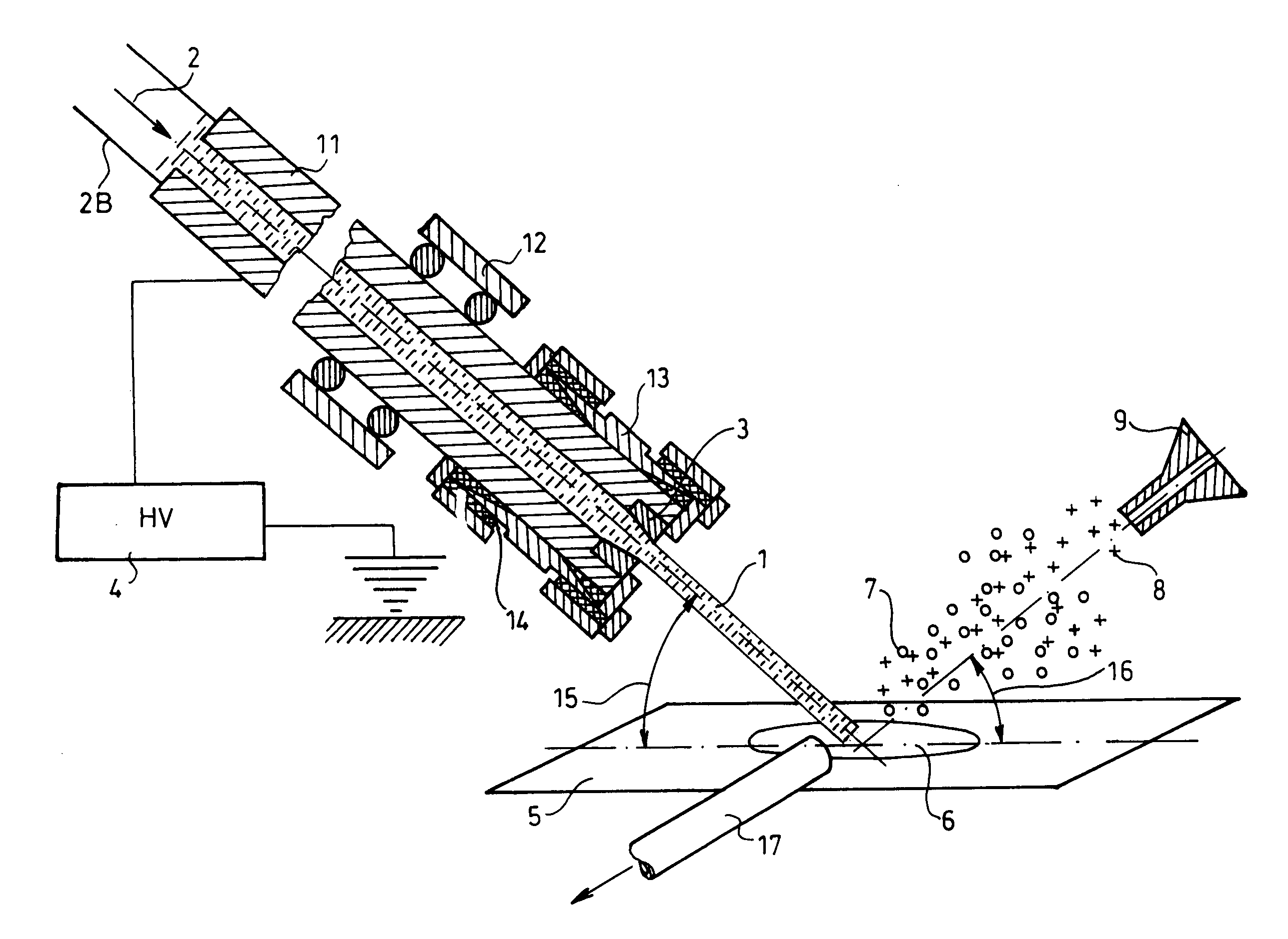
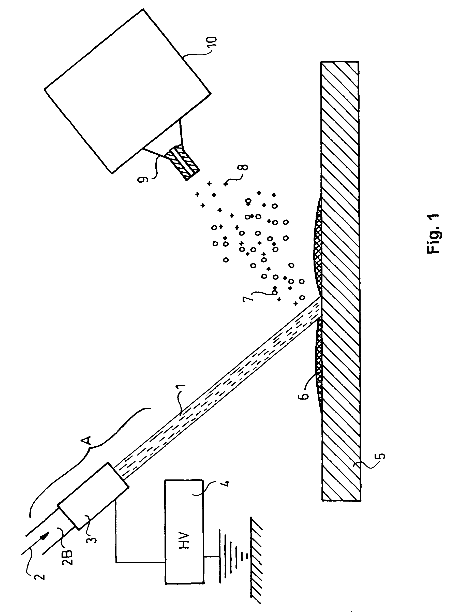
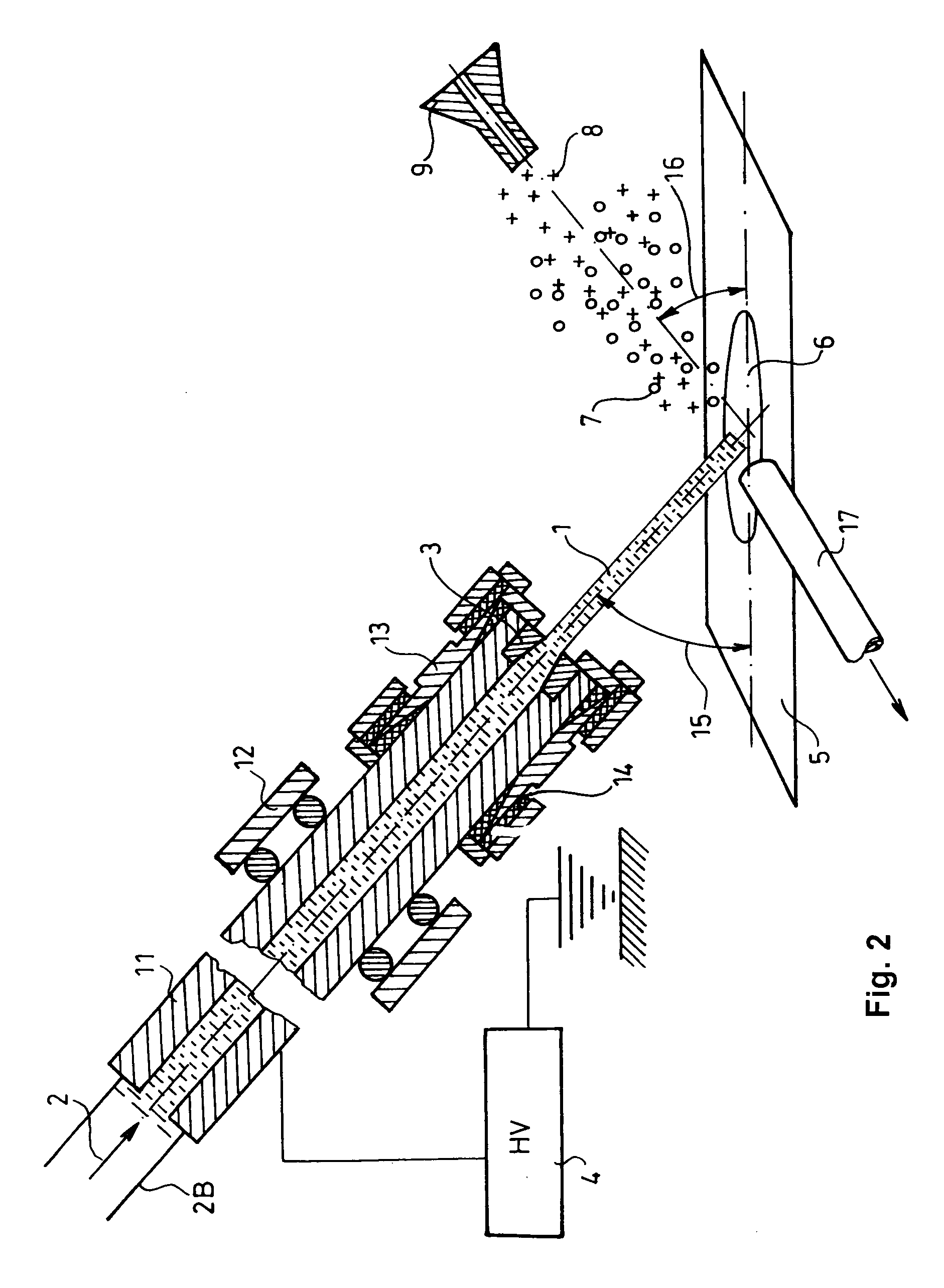
[0124]1.1. The Water Jet Desorption Ion Source for Mass Spectrometry Comprises the Following Parts:[0125]HPLC pump (Jasco),[0126] 1 / 16″ OD, 1 mm ID stainless steel tube (11),[0127]connectors (Swagelok, Upchurch) (13),[0128]seals (Swagelok, Upchurch) (14),[0129]5 μm ID sapphire nozzle (3),[0130]2 moving stages for 3D linear moving (Newport),[0131]rotating stage for rotation in one dimension (Newport),[0132]high-voltage power supply (Bertan) (4)[0133]HDPE tube, 1 / 16″ OD, 1 mm ID (17),[0134]membrane pump,[0135]mass spectrometer (Thermo Finnigan LCQ Duo).

[0136]1.2. Construction of Water Jet Desorption Ion Source for Mass Spectrometry

[0137]Schematic drawing of apparatus is shown on FIG. 2. Stainless steel 11 tube is connected to HPLC pump through HDPE tube and 3 nozzle is connected according to FIG. 2. The end of stainless steel tube having the nozzle is mounted on rotating stage utilizing sui...

example 2

Water Jet Desorption Ion Source for Mass Spectrometry to Define Spatial Distribution of the Concentration of Specific Compounds in a Sample

[0144]2.1. Water Jet Desorption Ion Source for Mass Spectrometry to Define Spatial Distribution of Concentration of Specific Compounds in a Sample Comprises the Following Parts:[0145]HPLC pump (Jasco),[0146] 1 / 16″ outer diameter, 1 mm internal diameter stainless steel tube, which is sealed on one end by welding in a length of 0.2 mm, and the sealed section is drilled through by means of laser drilling to form a 1 μm diameter circular cross-section orifice (11),[0147]connectors (Swagelok, Upchurch) (13),[0148]seals (Swagelok, Upchurch) (14),[0149]2 computer controlled moving stages for 3D linear moving (Newport),[0150]rotating stage for rotation in one dimension (Newport),[0151]high voltage power supply (Bertan) (4),[0152]HDPE 17 tube, 1 / 16″ outer diameter, 1 mm internal diameter,[0153]membrane pump,[0154]mass spectrometer (Thermo Finnigan LCQ Duo...

example 3

Surgical Device Based on Water Jet Desorption

[0162]3.1. Surgical Device Based on Water Jet Desorption Comprises the Following Parts (the Device is Shown in FIG. 4):[0163]HPLC pump (Jasco),[0164] 1 / 16″ outer diameter, 1 mm internal diameter stainless steel tube (11),[0165]connectors (Swagelok, Upchurch) (13),[0166]seals (Swagelok, Upchurch) (14),[0167]pulled silica capillary nozzle having 1 to 5 μm internal diameter (3),[0168]high voltage power supply (Bertan) (4),[0169]HDPE tube, 1 / 16″ outer diameter, 1 mm internal diameter (17),[0170]membrane pump,[0171]mass spectrometer (Thermo Finnigan LCQ Duo).

[0172]3.2. Construction of Surgical Device Based on Jet Desorption

[0173]Fused silica capillary having 0.32 mm outer diameter and 10 μm internal diameter is pulled to 1 μm outer diameter at one end (3) and the other end of it is connected to HDPE tube having 1 / 16″ outer diameter which is connected to HPLC pump. Copper tube (20) having lengths of 1 m, ⅛″ outer diameter and 2 mm internal diam...


PUM


Abstract

The invention relates to method and apparatus for production of gaseous ions from components of a condensed phase sample and analysis thereof, wherein one or more liquid jet(s) is / are directed to the surface of the sample to be investigated, where the impact of the liquid jet on the sample surface produces droplets carrying sample particles which are turned into gaseous ions via the evaporation of liquid or, if desired, by a subsequent ionization after the evaporation and the obtained sample particles are analyzed by a known method.

Description

[0001]This is the National Stage of International Application PCT / HU2007 / 000049, filed May 31, 2007.[0002]The subject of the invention is a method and apparatus for converting components of a condensed phase sample into gaseous ions and analysis thereof.[0003]During the implementation of the method according to the invention a high-velocity liquid jet is impacted with the surface of said sample. The liquid droplets formed at the impact of the liquid with the surface of the sample carry away the components of the sample (desorption step). The sample remaining after the evaporation of the solvent is a gaseous ion itself or it is convertible into gaseous ion by the use of an external effect—heat, electromagnetic effect etc. (optional step for providing gaseous ions). The obtained gaseous ions are analyzed, preferably by mass spectrometry or ion mobility spectrometry (detection step).PRIOR ART[0004]Mass spectrometric ionization methods have been traditionally developed for the analysis ...

Claims


Application Information

Patent Timeline
Patent Type & Authority Patents(United States)
IPC IPC(8): H01J49/00B01D59/44
CPCG01N1/286H01J49/0463H01J49/142G01N27/623G01N27/628
Inventor TAKÁTS, ZOLTÁN
Owner SEMMELWEIS EGYETEM
Why Eureka
Try Eureka