
Sample substrate for laser desorption ionization-mass spectrometry, and method and device both using the same for laser desorption ionization-mass spectrometry

a mass spectrometry and sample substrate technology, applied in the field of sample substrate for laser desorption ionization mass spectrometry, can solve the problems of difficult mass spectrometry of a sample molecule of interest, general problems, and difficulty in uniform application of samples, so as to achieve accurate measurement, enhance measurement sensitivity, and large specific surface area

Inactive Publication Date: 2013-10-15
HORI MASARU
View PDF7 Cites 10 Cited by
  • Summary
  • Abstract
  • Description
  • Claims
  • Application Information

AI Technical Summary

Benefits of technology

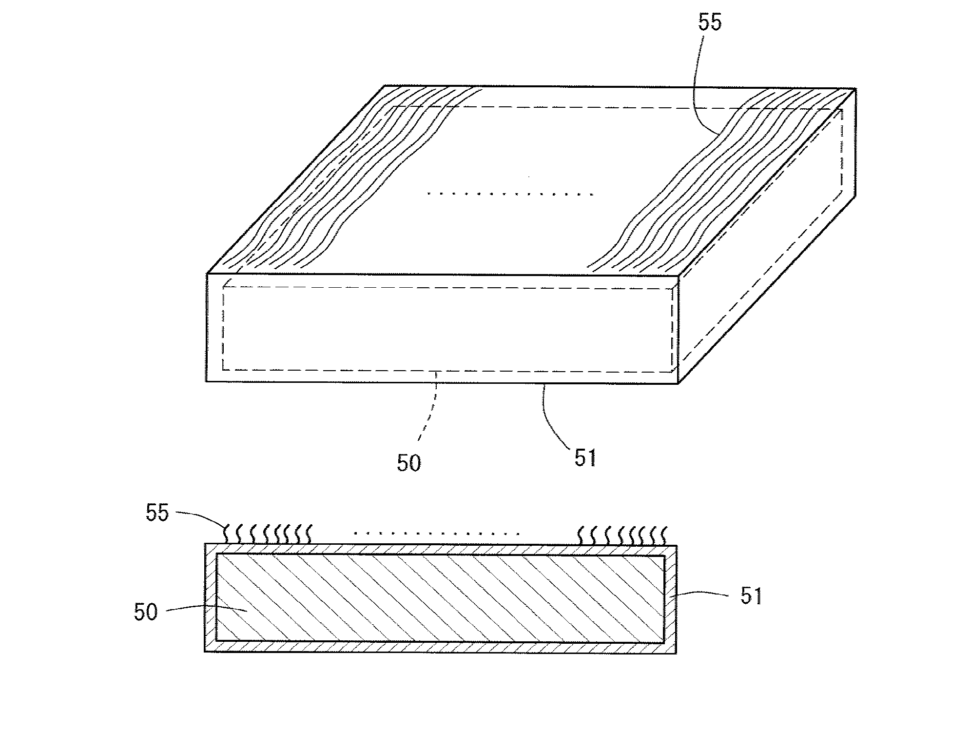
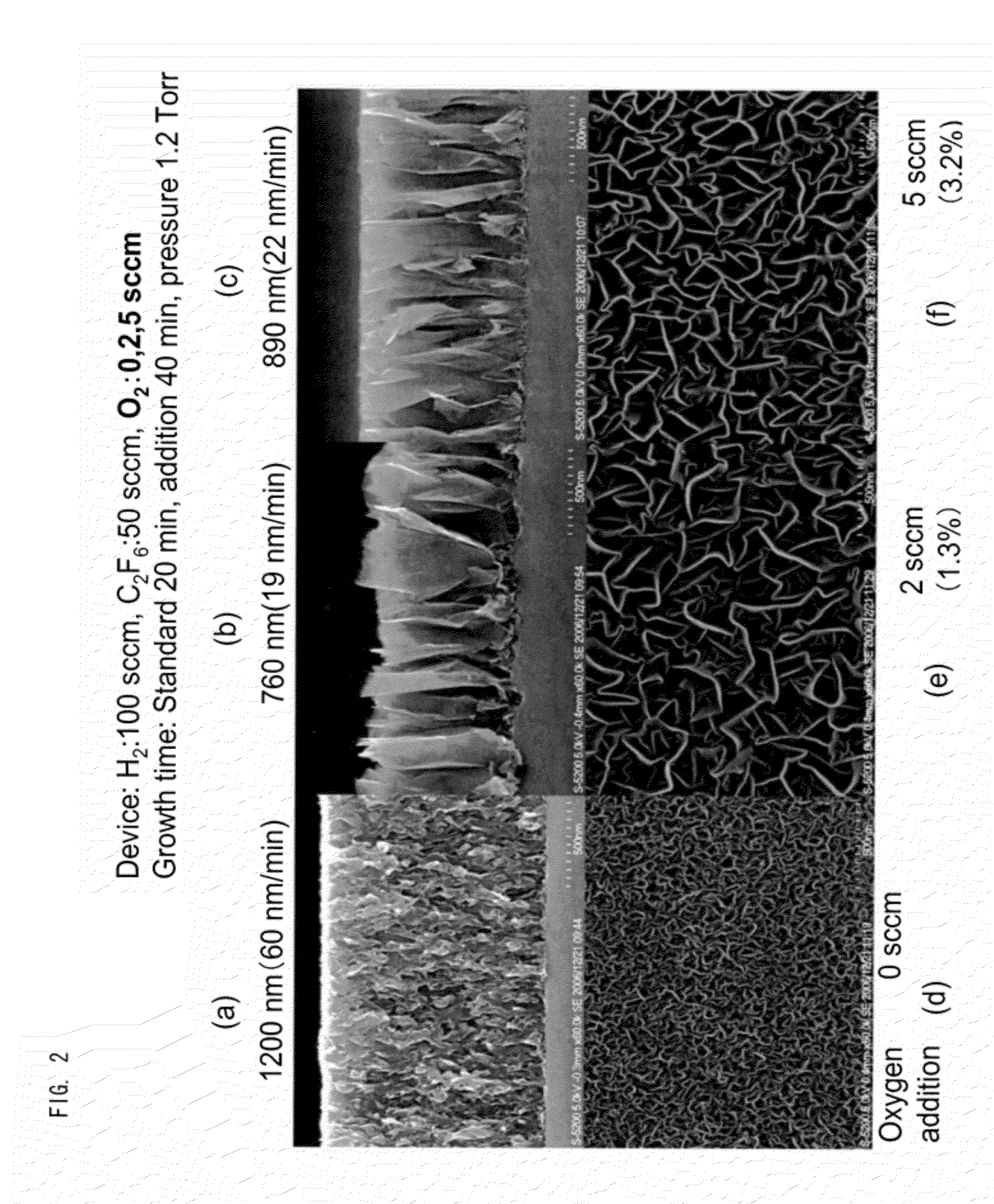
The present invention relates to a new sample substrate for laser desorption ionization mass spectrometry that can prevent interference peaks caused by the ionizing agent and enhance measurement sensitivity. The substrate has a stable surface and no surface instability, which ensures repetitive measurements. The substrate can be produced through a routine dry process such as plasma deposition and does not require a wet process such as etching. Additionally, a carbon nanowall structure can be easily produced with uniform in-plane density, which avoids locational variation in sensitivity.

Problems solved by technology

All these ions mask target ions to be detected, generally making mass spectrometry of a sample molecule of interest difficult.
Therefore, an analysis sample must be prepared with an appropriately selected matrix agent, and such selection is carried out on a trial and error basis, which is inconvenient.
In the micropowder method, since a suspension of the liquid sample and micropowder is applied onto a sample substrate for mass spectrometry, difficulty is encountered in uniformly applying the sample.
Particularly in the case of high-sensitivity mass spectrometry, failure to attain uniform application is generally problematic.
In addition, an ionization medium is scattered in an ion source chamber through laser light radiation, resulting in problematic contamination.
However, the ionization efficiency varies considerably depending on the conditions under which porous silicon has been formed, and great difficulty is encountered in production of sample substrates having the same porous structure at high reproducibility.
Thus, at present, DIOS-MS cannot necessarily be employed as a reliable mass spectrometric technique.
Such unionized molecules interfere with high-sensitivity measurement and make washing of the sample substrate after measurement difficult.
Failure in washing causes prevention of generation of peaks attributed to a precedent sample.
Thus, DIOS-MS is not necessarily a suitable technique for repeated sample measurement.
Therefore, the nano-wire-gold microparticle structure is prone to be broken by laser light irradiation in measurement or in a sample substrate washing step performed after measurement.
Thus, the nano-wire method is not necessarily a suitable technique for repeated sample measurement.
One problem involved in the technique is a small specific surface area of the flat substrate onto which a sample is applied, resulting in low sensitivity.
However, as described in the sections of “Background Art” and “Examples” in Patent Document 3, when graphite powder which has been subjected to no further treatment is employed as a matrix, graphite scatters to generate interference peaks, and the scattered graphite contaminates the ion source chamber, which is considerably problematic.
Due to conductivity, graphite as a contaminant provides electric discharge upon application of high voltage thereto for ion acceleration by the ion source chamber, and the electric discharge may give severe damage to relevant devices.
Therefore, an LDI-MS technique employing graphite powder is applied to a limited range of research.
Although scattering of graphite is prevented in the production procedure, the particle size, amount, and film thickness and graphite powder forming the graphite thin film cannot be controlled precisely or uniformly.

Method used


Image

  • Sample substrate for laser desorption ionization-mass spectrometry, and method and device both using the same for laser desorption ionization-mass spectrometry
  • Sample substrate for laser desorption ionization-mass spectrometry, and method and device both using the same for laser desorption ionization-mass spectrometry
  • Sample substrate for laser desorption ionization-mass spectrometry, and method and device both using the same for laser desorption ionization-mass spectrometry

Examples


example 1

Application to Industrial Product (1)

[0113]A phenylenediamine anti-oxidant [4,4′-(α,α-dimethylbenzyl)diphenylamine] was dissolved in tetrahydrofuran (THF), to thereby prepare a 1-mg / mL sample solution. The sample solution (1 mL) was applied to a carbon nanowall element (i.e., a sample substrate containing carbon nanowalls formed on the surface so as to stand from the surface, the same applies to the following) and dried. The thus-treated element was affixed to a sample base for MALDI measurement, and the structure was placed in a time-of-flight type mass spectrometer (Voyager DE-PRO) equipped with an N2 laser for analysis. The material of the substrate on which carbon nanowalls were formed was a conductive silicon substrate. The substrate assumed the shape of a square (10 mm×10 mm). The same substrate was also employed in the following Examples. However, needless to say, when there is employed a substrate made of a material other than silicon (e.g., an insulating silicon substrate, ...

example 2

Application to Industrial Product (2)

[0117]A hindered phenol anti-oxidant (Irganox 1035, registered trademark) was dissolved in chloroform containing sodium iodide in a concentration of 0.5 mg / mL, to thereby prepare a 0.5-mg / mL sample solution. The sample solution (1 mL) was applied to a carbon nanowall element and dried. The thus-treated element was affixed to a sample base for MALDI measurement, and the structure was placed in a time-of-flight type mass spectrometer (Voyager DE-PRO) equipped with an N2 laser for analysis.

[0118]A mass spectrum of the anti-oxidant sample observed by use of the carbon nanowall element is shown in FIG. 6. [M+Na]+ ion of the anti-oxidant sample was clearly observed at an m / z of 665.4. As is clear from the spectrum, the anti-oxidant sample was found to be suitably analyzed through mass spectrometry employing the carbon nanowall element as an ionization device.

example 3

Application to Industrial Product (3)

[0119]A polyoxyethylene nonionic surfactant (Triton X-100, registered trademark) was dissolved in chloroform containing sodium iodide in a concentration of 0.5 mg / mL, to thereby prepare a 0.5-mg / mL sample solution. The sample solution (1 mL) was applied to a carbon nanowall element and dried. The thus-treated element was affixed to a sample base for MALDI measurement, and the structure was placed in a time-of-flight type mass spectrometer (Voyager DE-PRO) equipped with an N2 laser for analysis. Note that the surfactant is represented by C8H17—PhO—(CH2—CH2—O)n—H (wherein Ph represents a phenyl group, and n is the number of repeating units).

[0120]A mass spectrum of the surfactant sample observed by use of the carbon nanowall element is shown in FIG. 7. [M+Na]+ ion of the surfactant sample was clearly observed at a peak m / z of 650 or thereabout within a range of 400 to 1,200. Notably, peaks observed with intervals of mass of 44 are attributed to pol...


PUM


Abstract

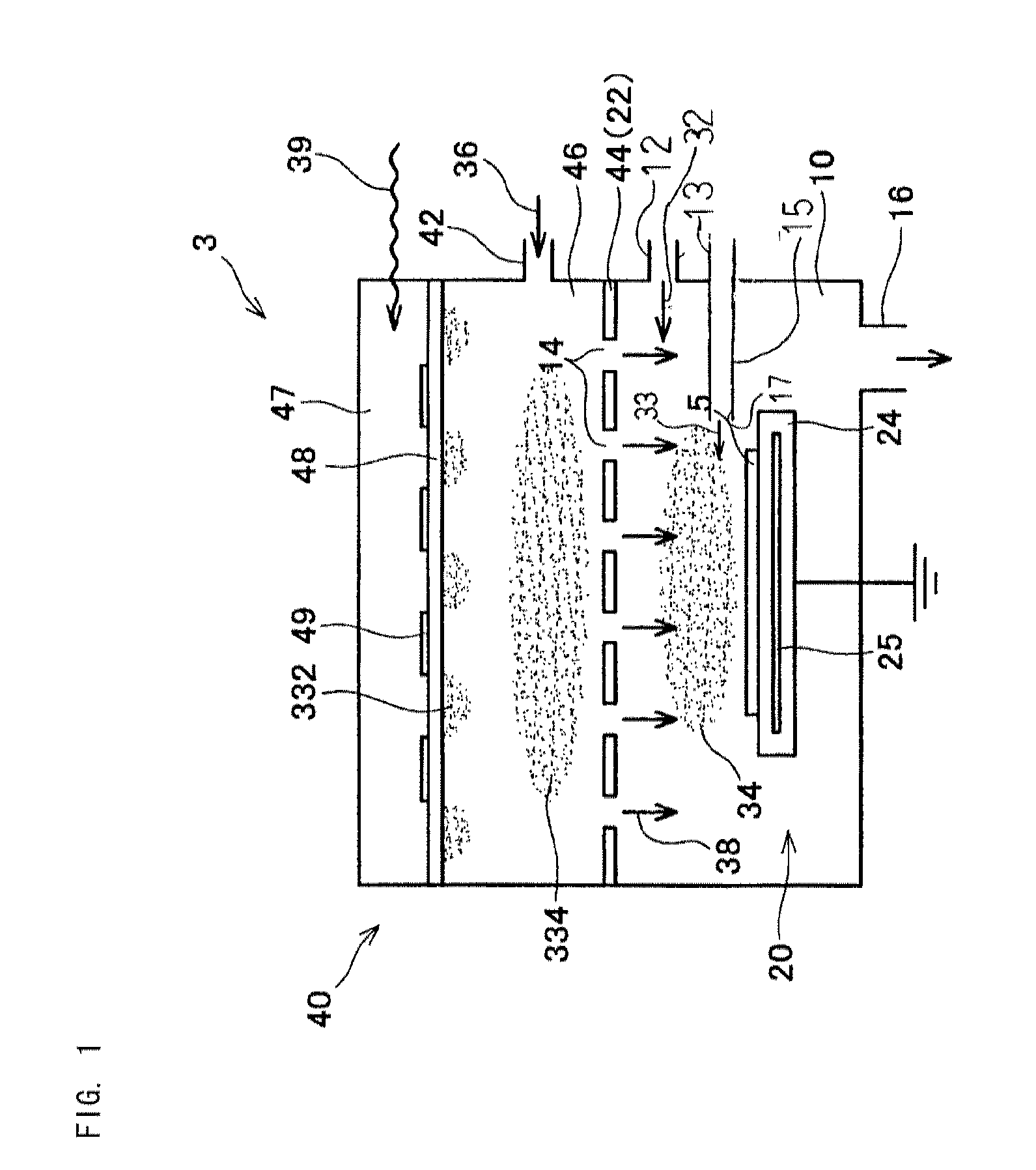
An object of the present invention is to provide a sample substrate for laser desorption ionization mass spectrometry for LDI-MS which substrate enables mass spectrometric analysis of a sample correctly at high sensitivity without generating interference peaks upon irradiation of the sample to laser light and uniform application of the sample onto a base. Another object of the invention is to provide a mass spectrometer (device) employing the sample substrate.In the sample substrate for laser desorption ionization mass spectrometry, the sample substrate is formed of a base and carbon nanowalls having wall surfaces onto which a sample to undergo mass spectrometry is applied, wherein the carbon nanowalls are formed on the base so as to stand on the base. The surfaces of carbon nanowalls serve as an ionization medium and hydrophilized. By use of the sample substrate, mass spectrometry of a sample having a wide range (high to low) molecular weight can be reliably performed at high precision and sensitivity.

Description

TECHNICAL FIELD[0001]The present invention relates to a sample substrate for laser desorption ionization mass spectrometry, and to a method and device for laser desorption ionization mass spectrometry employing the sample substrate. More particularly, the invention relates to such a sample substrate which employs no matrix for assisting soft ionization and to an analytical method and an analysis device employing the sample substrate.BACKGROUND ART[0002]Hitherto, the molecular weight of a bio-substance (e.g., protein, peptide, saccharide, or oligonucleotide), a polymer, or a synthetic polymer has been known to be correctly determined through laser desorption ionization mass spectrometry (LDI-MS) by means of a measurement device therefor.[0003]In the analytical method, individual molecules of the sample are required to be ionized through laser radiation without decomposing the molecules. In a procedure typically employed to avoid decomposition of sample molecules, a sample is applied ...

Claims


Application Information

Patent Timeline
IPC IPC(8): H01J49/00
CPCG01N27/622G01N27/00
Inventor HORI, MASARUSATO, HIROAKITOYOSHIMA, YASUTAKEHIRAMATSU, MINEO
Owner HORI MASARU
Learn More