
Spin-transfer torque magnetic random access memory having magnetic tunnel junction with perpendicular magnetic anisotropy

a magnetic random access memory and spin-transfer torque technology, applied in the field of spin-transfer torque magnetic random access memory (mram), can solve the problems of high write current, preventing its adoption in consumer devices, and complex cell architectur

Active Publication Date: 2013-11-26
AVALANCHE TECH
View PDF4 Cites 30 Cited by
  • Summary
  • Abstract
  • Description
  • Claims
  • Application Information

AI Technical Summary

Benefits of technology

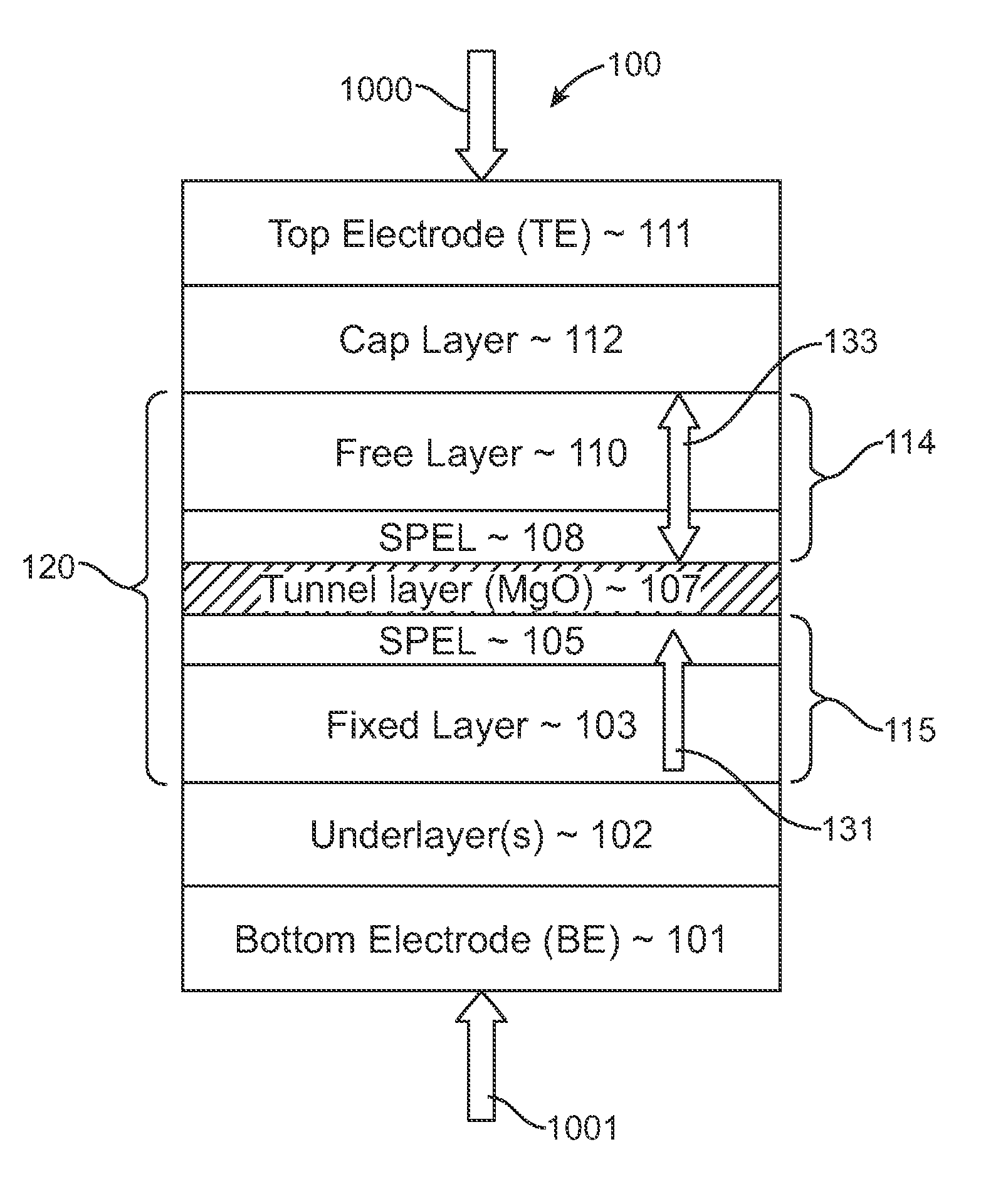
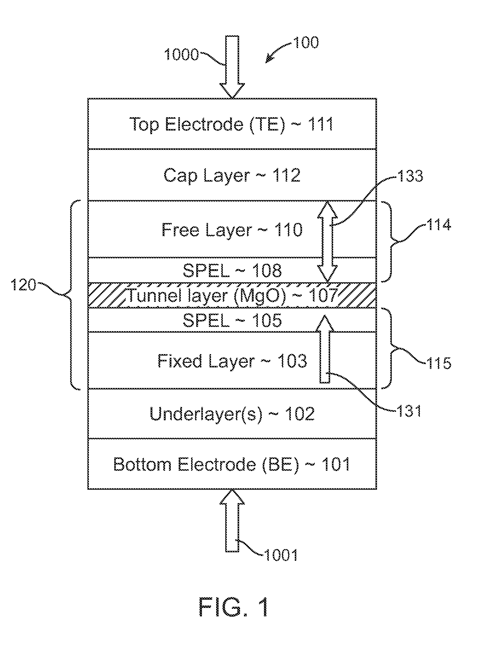
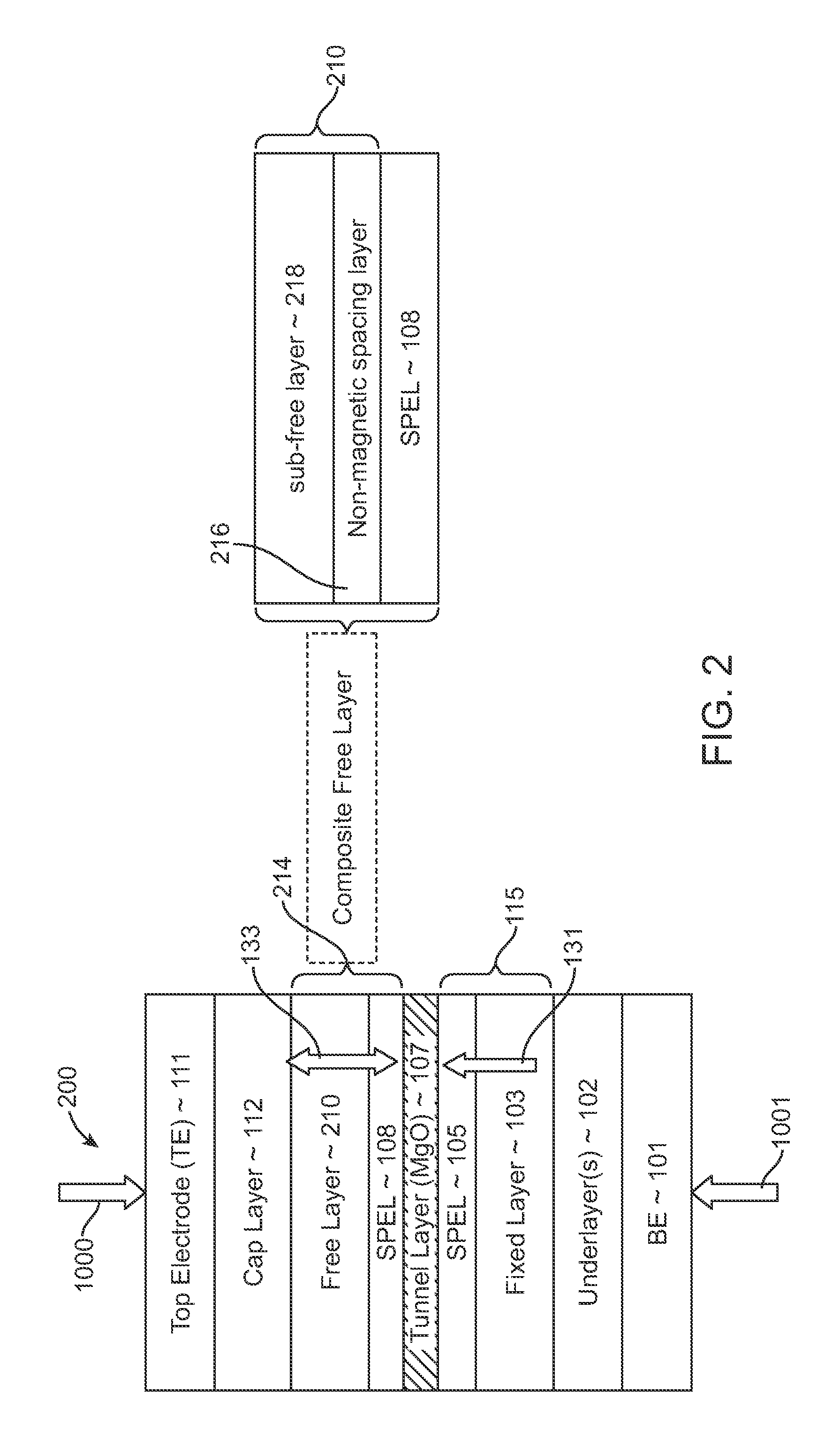
The present invention is a method and structure for a magnetic storage memory device that reduces the switching current needed for magnetic memory. The invention includes a spin-torque transfer memory random access memory (STTMRAM) element with a fixed layer and a composite free layer made of various materials. The magnetization direction of the composite free layer is perpendicular to the substrate. The invention allows for writing data on the STTMRAM element using a bidirectional electric current to switch the second magnetization between parallel and anti-parallel states relative to the first magnetization. The invention provides a way to reduce the switching current needed and improve the performance of magnetic memory devices.

Problems solved by technology

While STTMRAM are expected to be a universal memory solution, various hurdles stand in the way.
The programming current of STTMRAM is still very high as main memory, therefore, the cell size is too large thereby preventing its adoption in consumer devices.
Scaling STTMRAM below 65 nm is ideal; however reducing the programming current and shrinking the cell size introduces a variety of issues, such as thermal instability.
The main hurdles associated with field switched MRAM are its more complex cell architecture, which utilizes bypass line and remote write lines.
Additional hurdles include its high write current (currently in the order of milliamps (mA)) and poor scalability, which cannot scale beyond 65 nano meters (nm).
One of the challenges for implementing STT, is that during writing mode, such memory used in high-density and high-speed memory applications, require substantial reduction of the intrinsic current density to switch the magnetization of the free layer while maintaining high thermal stability, which is required for long-term data retention.
Second, smaller voltage across MTJ decreases the probability of tunneling barrier degradation and breakdown, ensuring write endurance of the device.
Incorporation of MgO-based MTJ with conventional perpendicular anisotropy material(s), such as FePt, into STTMRAM with such MTJ designs cause high damping constant, high magnetic anisotropy leading to undesirably high switching current density.
Furthermore, during manufacturing, conventional higher ordering transformation temperature required for forming L10 order structure could undesirably degrades or even obliterates tunneling magneto-resistance (TMR) performance.

Method used


Image

  • Spin-transfer torque magnetic random access memory having magnetic tunnel junction with perpendicular magnetic anisotropy
  • Spin-transfer torque magnetic random access memory having magnetic tunnel junction with perpendicular magnetic anisotropy
  • Spin-transfer torque magnetic random access memory having magnetic tunnel junction with perpendicular magnetic anisotropy

Examples


Embodiment Construction

[0021]In the following description of the embodiments, reference is made to the accompanying drawings that form a part hereof, and in which is shown by way of illustration of the specific embodiments in which the invention may be practiced. It is to be understood that other embodiments may be utilized because structural changes may be made without departing from the scope of the present invention. It should be noted that the figures discussed herein are not drawn to scale and thicknesses of lines are not indicative of actual sizes.

[0022]In accordance with an embodiment of the present invention, a spin-transfer torque magnetic random access memory (STTMRAM) element includes a magnetic tunnel junction (MTJ) having a fixed layer and a free layer wherein the magnetic orientation of fixed layer and free layer is substantially perpendicular to the plane of the layers. The selection of the magnetic alloy for use in each of the fixed layer and the free layer, as disclosed herein, advantageo...


PUM

PropertyMeasurementUnit
thicknessaaaaaaaaaa
magnetizationaaaaaaaaaa
crystallineaaaaaaaaaa

Abstract

A spin-torque transfer memory random access memory (STTMRAM) element includes a fixed layer formed on top of a substrate and a tunnel layer formed upon the fixed layer and a composite free layer formed upon the tunnel barrier layer and made of an iron platinum alloy with at least one of X or Y material, X being from a group consisting of: boron (B), phosphorous (P), carbon (C), and nitride (N) and Y being from a group consisting of: tantalum (Ta), titanium (Ti), niobium (Nb), zirconium (Zr), tungsten (W), silicon (Si), copper (Cu), silver (Ag), aluminum (Al), chromium (Cr), tin (Sn), lead (Pb), antimony (Sb), hafnium (Hf) and bismuth (Bi), molybdenum (Mo) or rhodium (Ru), the magnetization direction of each of the composite free layer and fixed layer being substantially perpendicular to the plane of the substrate.

Description

CROSS REFERENCE TO RELATED APPLICATIONS[0001]This application claims priority to U.S. Provisional Patent Application No. 61 / 138,493, filed on Dec. 17, 2008 by Ranjan et al. and is a continuation-in-part of U.S. patent application Ser. No. 11 / 674,124, filed on Feb. 12, 2007 and entitled “Non-uniform switching based non-volatile magnetic based memory” by Rajiv Yadav Ranjan and a continuation-in-part of U.S. patent application Ser. No. 11 / 739,648, filed on Apr. 24, 2007, and entitled “Non-volatile magnetic memory with low switching current and high thermal stability” by Rajiv Yadav Ranjan and a continuation-in-part of U.S. patent application Ser. No. 11 / 776,692, filed on Jul. 12, 2007, and entitled “Non-Volatile Magnetic Memory Element With Graded Layer” by Rajiv Yadav Ranjan, which are all incorporated herein by reference as though set forth in full.BACKGROUND OF THE INVENTION[0002]1. Field of the Invention[0003]The present invention relates to a spin-transfer torque (STT) magnetic ra...

Claims


Application Information

Patent Timeline
Patent Type & Authority Patents(United States)
IPC IPC(8): G11C11/00H01L29/82H10B69/00
CPCB82Y10/00B82Y25/00G11C11/16H01L27/228H01L43/08G11C11/161G11C11/1675H10B61/22H10N50/10
Inventor RANJAN, RAJIV YADAVMALMHALL, ROGER KLAS
Owner AVALANCHE TECH
Learn More