
Method of manufacturing relief printing plate and printing plate precursor for laser engraving

a printing plate and laser engraving technology, applied in the direction of printing press parts, instruments, photosensitive materials, etc., can solve the problems of low productivity, slow laser engraving speed, and time-consuming plate making process for the production of original image films, etc., to achieve high output, high output, and high output

Inactive Publication Date: 2014-03-11
FUJIFILM CORP
View PDF25 Cites 0 Cited by
  • Summary
  • Abstract
  • Description
  • Claims
  • Application Information

AI Technical Summary

Benefits of technology

The present invention provides a method and device for manufacturing a laser engraved printing plate that is highly sensitive to laser, while also being cost-effective and productive. This is achieved by using a combination of fiber laser and CO2 laser in an invention that simplifies the manufacturing process and eliminates the need for complex and expensive equipment. The invention is a relief printing plate precursor that is especially suitable for this method.

Problems solved by technology

In the case of producing a relief printing plate by analogue plate making, since an original image film using a silver salt material is needed in general, the plate making process requires time and costs for the production of original image films.
However, in this method, since high energy is required to form a relief having a concave-convex structure which can withstand the printing pressure, on a relief forming layer having a predetermined thickness, and the speed of laser engraving is slow, the method has a problem of low productivity as compared to the methods in which image formation involves the use of a mask.
However, due to being a foamed material having low density, there is a concern to the obtained printing plate with respect to lack of strength or the like, which might cause seriously impaired print durability.
However, when such a polymeric filler is used, surface irregularities are generated on the surface of the printing plate precursor, and seriously affect the printing quality.
However, the thermal stability of the material is insufficient.
As will be understood from the above, when measures such as reducing the density of a relief forming layer or employing materials having low thermal resistance or high thermal response are taken in order to improve the sensitivity to laser of a relief forming layer, there is cause for concern that the storage stability or the physical properties of the resulting relief layer may be impaired.
However, although CO2 laser enables high output, it can be difficult to conduct high-speed drawing of an image while also maintaining high output, as a result of which, improvements in productivity have not been achieved yet.
However, the combined approach requires more complex operation and higher costs for the laser, which negates any advantages gained thereby when evaluated in terms of the overall improvement in productivity.

Method used


Image

  • Method of manufacturing relief printing plate and printing plate precursor for laser engraving
  • Method of manufacturing relief printing plate and printing plate precursor for laser engraving
  • Method of manufacturing relief printing plate and printing plate precursor for laser engraving

Examples


synthetic example 1

Synthesis of Polyurethane resin P-1

[0395]8.2 g (0.05 mol) of 2,2-Bis(hydroxymethyl)butanoic acid and 13.0 g (0.05 mol) of the following diol compound (1) were dissolved in 100 ml of N,N-dimethylacetamide in a 500-ml three-necked round bottom flask equipped with a condenser and a stirrer. 25.5 g (0.102 mol) of 4,4-diphenylmethane diisocyanate and 0.1 g of dibutyl tin dilaurylate were added to the resultant, followed by heating at 100° C. for 8 hours with stirring. After that, the resultant was diluted with 100 ml of N,N-dimethylformamide and 200 ml of methyl alcohol followed by stirring for 30 minutes. The reaction solution was poured into 3 liters of water with stirring so that a white polymer was precipitated. The polymer was taken by filteration, washed with water and dried under vaccum to give 37 g of polymer.

[0396]A molecular weight of the polymer was measured by means of gel permeation chromatography (GPC) and turned out to be 95,000 in terms of the weight-average molecular wei...

example 9

[0424]50 parts by weight of polyvinyl butyral (trade name: #3000-1, manufactured by Denki Kagaku Kogyo) as a binder polymer, 20 parts by weight of diethylene glycol as a plasticizer and 30 parts by weight of ethanol as a solvent were placed in a three-necked flask equipped with a stirring spatula and a cooling pipe and heated at 70° C. for 120 minutes to dissolve the binder polymer.

[0425]15 parts by weight of an ethylenic unsaturated monomer (trade name: LIGHT ACRYLATE 14EG-A, diacrylate of polyethylene glycol 600, manufactured by Kyoeisha Kagaku), 15 parts by weight of polyalkylene glycol(meth)acrylate monomer (trade name: BLEMMER PE-200, manufactured by NOF), 1.5 parts by weight of tert-butyl peroxide (trade name: PERBUTYL Z, manufactured by NOF) as a polymerization initiator and 0.005 part by weight of ammonium N-nitrosophenyl hydroxylamine (trade name: Q-1300, manufactured by Wako Pure Chemical Industries), 3 parts by weight of ZnCl2 (manufactured by Wako Pure Chemical Industrie...

example 10

[0427]50 parts by weight of styrene-butadiene polymer (trade name: NIPOL NS 116R, manufactured by Nippon Zeon) as a binder polymer, 0.7 part by weight of carbon black (SEAST 9H SAF-HS, manufactured by Tokai Carbon) and 30 parts by weight of methyl ethyl ketone were placed in a three-necked flask equipped with a stirring spatula and a cooling pipe and stirred for 30 minutes to give an application solution composition for forming a relief forming layer having fluidity. This application solution composition for forming a relief forming layer for Example 10 was flown on the surface of the second adhesive layer side of the support which was the same as that used in Example 1 and dried for 1 hour in an oven set at 100° C. to form a layered body having a non-crosslinked relief forming layer having a thickness of about 1,100 μm, which includes a thickness of the support, so that a printing plate precursor 10 for relief printing plate for laser engraving was prepared.


PUM


Abstract

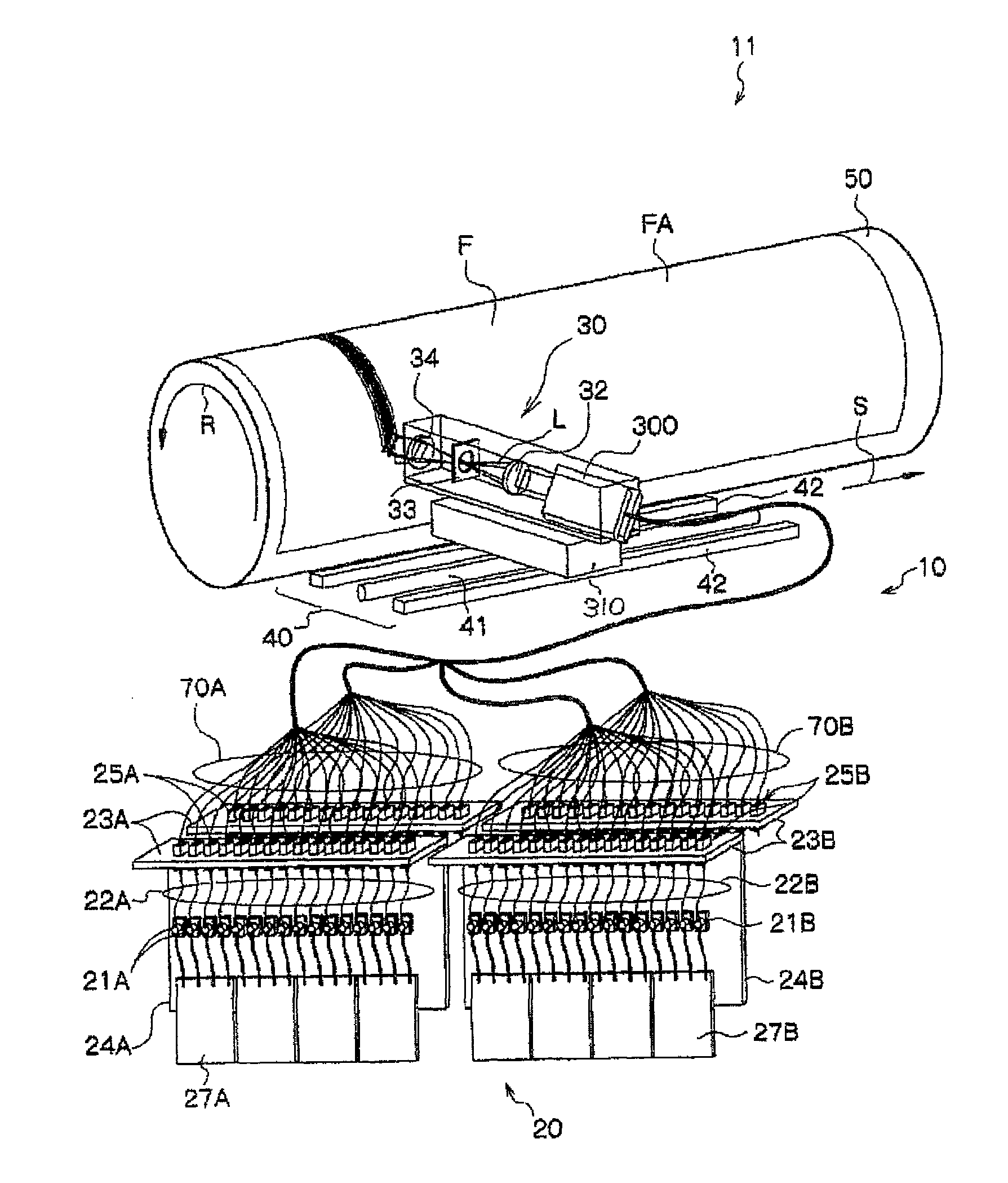
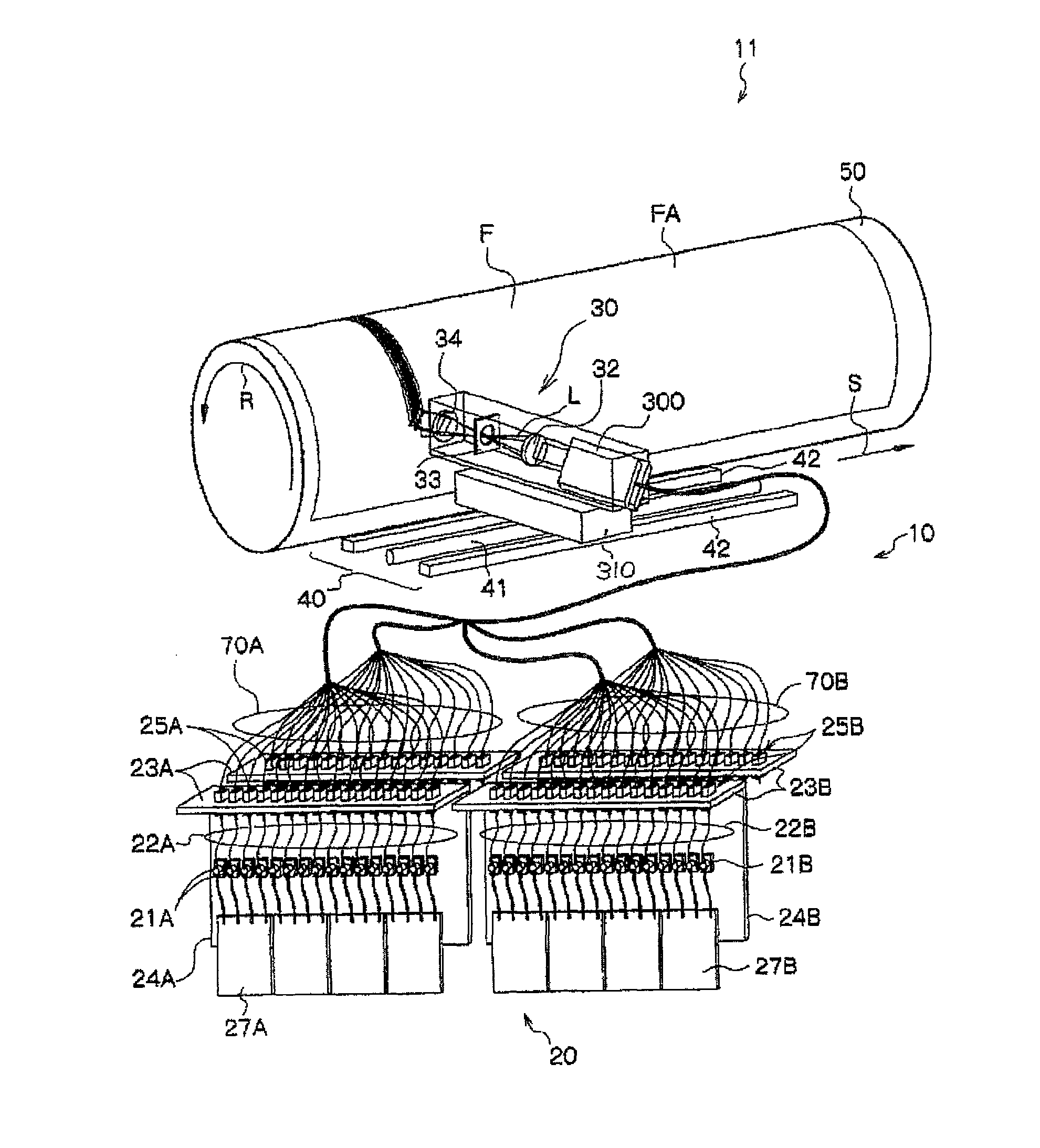
The invention provides a method of manufacturing a relief printing plate having at least engraving an area which is in a relief forming layer of a relief printing plate precursor for laser engraving and is to be exposed by scanning exposure using a fiber-coupled semiconductor laser which emits laser beam with a wavelength of 700 nm to 1,300 nm. The relief printing plate precursor has at least a relief forming layer provided over a support, and the relief forming layer contains at least a binder polymer and a photo-thermal conversion agent. The invention further provides a relief printing plate precursor for laser engraving which can be used in the method of manufacturing a relief printing plate.

Description

CROSS-REFERENCE TO RELATED APPLICATION[0001]This application claims priority under 35 USC 119 from Japanese Patent Application Nos. 2008-15457 filed on Jan. 25, 2008 and 2008-211830 filed on Aug. 20, 2008 the disclosures of which are incorporated by reference herein.BACKGROUND OF THE INVENTION[0002]1. Technical field[0003]The present invention relates to a method of manufacturing a relief printing plate and a printing plate precursor for laser engraving, which is used for the manufacturing method.[0004]2. Description of the Related Art[0005]As a method for forming a printing plate by forming a concave-convex structure on a photosensitive resin layer laminated on the surface of a support, a method of exposing a relief forming layer which has been formed using a photosensitive composition, to ultraviolet radiation through an original image film so as to selectively cure image areas, and removing uncured parts by means of a developer solution, that is, so-called “analogue plate making”...

Claims


Application Information

Patent Timeline
Patent Type & Authority Patents(United States)
IPC IPC(8): B41F33/00B41N1/00B41N1/12B41C1/05G03F7/26G03F7/00
CPCB41C1/05
Inventor TASHIRO, HIROSHISUGASAKI, ATSUSHIYAMAMOTO, HISAO
Owner FUJIFILM CORP
Learn More