
Method and apparatus for removing carbon dioxide gas from coal combustion power plants

a technology of carbon dioxide gas and coal combustion power plant, which is applied in the direction of lighting and heating apparatus, sublimation, separation processes, etc., can solve the problems of inability to determine the exact percentage of the greenhouse, unfavorable environmental protection, and serious environmental hazards, so as to increase the efficiency of the fuel driven turbine generator, reduce the effect of energy consumption and greater mass flow

Inactive Publication Date: 2017-10-03
ENIS BEN M +1
View PDF14 Cites 1 Cited by
  • Summary
  • Abstract
  • Description
  • Claims
  • Application Information

AI Technical Summary

Benefits of technology

The patent describes a process called Integrated Gasification Combined Cycle (IGCC) that can produce energy and environmentally friendly fuel, such as hydrogen. Heat exchangers are used to transfer heat from the air compression device to a steam turbine generator, which improves the efficiency of the entire system. This results in more efficient production of electricity.

Problems solved by technology

At the same time, there are also serious environmental hazards and consequences associated with the use of coal, including the emission of carbon dioxide gas which can lead to global warming and other climate changes.
), thereby making the earth uninhabitable.
It is not possible to determine the exact percentage of the greenhouse effect caused by any one gas because the influences of the various gases are not additive.
The problem at hand, nevertheless, is that the process of capturing, transporting and storing carbon dioxide gas from coal combustion power plants can dramatically raise energy consumption costs and cause serious health and environmental issues and concerns.
Indeed, it has been discovered that capturing CO2 from smokestacks and compressing it for transport can be one of the most energy-intensive parts of the process.
It is also insufficient to simply place the smokestacks of a coal plant upside down as suitable underground reservoirs do not necessarily lie beneath the world's power stations.
And manufacturing and installing these thousands of miles of pipelines will require a substantial amount of cost and effort.
Moreover, it will take not only more research to find out which reservoirs are suitable for storage and which ones aren't, but the injection of CO2 into underground reservoirs and the monitoring of the transport network (today's pipelines are patrolled by plane every two weeks), as well as the transportation of gas by shipping or pipeline, will typically require significant effort and expense.
Not only would these rocks have to be mined and transported to coal plants, but the amount of industrial wastes and mining tailings that can be salvaged—for example, fuel ash from coal plants or de-inking ash from the paper industry—are too small to substantially help offset the cost of the mining and transporting that would be required.
Nevertheless, the results of a careful study of the economic feasibility of such processes now show that injecting flue gas into unminable coal bed seams to recover methane from coal bed methane (CBM) fields is only marginally economical, and will not significantly contribute to the world's carbon dioxide sequestration needs.
Taking all of the above factors into account, it is estimated that Carbon Capture and Storage will probably raise energy consumption in any given application by as much as fifty percent, and therefore, even if all of the CO2 can eventually be separated and stored, such an increase in energy consumption and costs may be too high of a price to pay to keep the environment clean.

Method used


Image

  • Method and apparatus for removing carbon dioxide gas from coal combustion power plants
  • Method and apparatus for removing carbon dioxide gas from coal combustion power plants
  • Method and apparatus for removing carbon dioxide gas from coal combustion power plants

Examples


example one

[0142]In a simple version of the proposed solution, the CTT device can be located in close proximity to the coal-combustion plant and use a minimal amount of power from the coal-combustion power plant to drive the CTT compressor. In this respect, FIG. 9 shows the compressor, turbo compressor and turbo expander CTT device with their associated heat exchangers, wherein the chart shows the thermodynamic state for each step in the CTT process.

[0143]It is an objective of this device to use two commercially available devices: (1) A gas compressor, and (2) A coupled turbo compressor and turbo expander set as a single CTT device to freeze the carbon dioxide derived from the IGCC. FIG. 9 shows how the power available from the turbo expander (28,772 kW) is appropriately matched to the power required by the turbo compressor (minus 27,859 kW). The chart at the top shows the compressor rating at 27,444 kW. However, there is recoverable waste heat of minus 4,115 kW from the compressor and minus 2...

example two

[0151]This example considers the limitations imposed by the compression available across each turbo compressor impeller disc and imposed by the expansion available across each turbo expander impeller disc. In particular, the boundary layer attached to each wall of the fluted vane is limited in terms of pressure ratio before it detaches from the wall. Furthermore, since there is power transfer from the turbo expander to the turbo compressor during its steady state “free spooling” mode, it is necessary to match two sets of turbo expander and turbo compressor combinations, wherein each combination has a separate power rating.

[0152]FIG. 13 shows the compressor intake of 14.696 psia and 70 degrees F. ambient air (Point A) to 50 psia and 247 degrees F. compressed air (Point C). The isentropic compression process would have resulted in a higher temperature of 291 degrees F. However, there were temperature drops related to the imperfect compression process and heat transfer to the body of t...


PUM

PropertyMeasurementUnit
poweraaaaaaaaaa
poweraaaaaaaaaa
diameteraaaaaaaaaa

Abstract

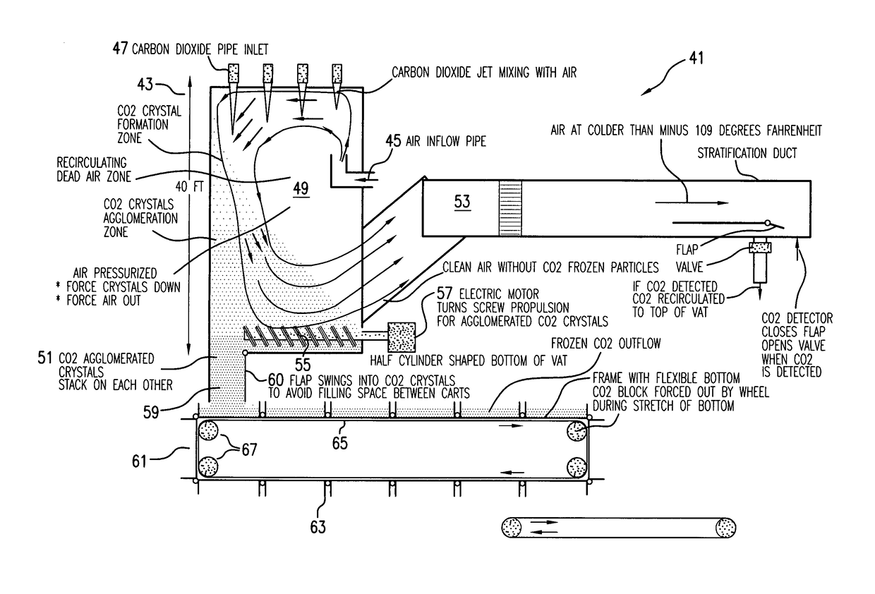
The invention relates to a method and apparatus for removing CO2 gas emissions from a coal combustion power plant, comprising a means for physically removing the CO2 gas from the coal, and then using a turbo compressor and turbo expander device to produce super chilled air, which can then be mixed with the CO2 gas to form frozen CO2 crystals which can agglomerate together to form dry ice blocks, wherein the ice blocks can be easily transported and stored, and / or used for commercial purposes (such as for the beverage industry). The heating (compression) and cooling (expansion) processes preferably generate additional energy which can then be used to offset the substantial costs associated with separating the CO2 gas from the coal.

Description

RELATED APPLICATION[0001]This application claims priority from U.S. Provisional Application Ser. Nos. 61 / 011,955, filed Jan. 23, 2008, and 61 / 195,418, filed Oct. 7, 2008, which are incorporated herein by reference in their entirety.BACKGROUND OF THE INVENTION[0002]At the current rate of usage, there is estimated to be about 300 years of coal deposits left in mines across the U.S.A. Coal is a valuable natural resource that represents one of the most abundant and efficient sources of energy available in the U.S. today. At the same time, there are also serious environmental hazards and consequences associated with the use of coal, including the emission of carbon dioxide gas which can lead to global warming and other climate changes.[0003]Greenhouse gases are found in the earth's atmosphere and contribute to the greenhouse effect. In the absence of the greenhouse effect, the mean temperature of the earth could be reduced to about minus 19 degrees C. (or minus 2 degrees F.) rather than ...

Claims


Application Information

Patent Timeline
Patent Type & Authority Patents(United States)
IPC IPC(8): F25J1/00B01D7/02B01D53/73F23J15/02F25J3/06C01B32/50C01B32/55
CPCB01D53/73B01D7/02Y02C10/08Y02C10/10Y02C10/12Y02C10/14Y02E20/326Y02P70/34B01D2257/504F23J15/02F25J1/007F25J3/067F25J2210/70F25J2215/80F25J2220/80F25J2220/84F25J2260/80Y02C10/00Y02C10/02Y02C10/04Y02C10/06Y02C20/40Y02E20/32Y02P70/10
Inventor ENIS, BEN M.LIEBERMAN, PAUL
Owner ENIS BEN M
Learn More