A Zn-Ni liquid battery

A flow battery, flow battery technology, applied in battery electrodes, alkaline batteries, battery pack components, etc., can solve the problems of reduced discharge rate, low performance stability, nickel electrode swelling, etc., to achieve high energy density and High power density, high energy utilization efficiency, and the effect of eliminating concentration polarization

Active Publication Date: 2008-02-20
NO 63971 TROOPS PLA +1
View PDF1 Cites 60 Cited by
  • Summary
  • Abstract
  • Description
  • Claims
  • Application Information

AI Technical Summary

Problems solved by technology

[0004] In the traditional zinc-nickel battery, the zinc electrode is rolled from zinc oxide (metal zinc powder), additives and polytetrafluoroethylene emulsion (70% porosity). When discharging, the zinc electrode generates zinc oxide and zinc hydroxide. These products A large amount of zinc is dissolved in strong alkaline electrolyte, and zincate has a high density and tends to sink; as the charge and discharge cycle proceeds, the upper part of the electrode is consumed and becomes thinner due to the loss of active materials; a large amount of zinc is deposited on the lower

Method used


Image

  • A Zn-Ni liquid battery

Examples


example 1

[0033] Positive electrode preparation

[0034]Mix the conductive agent carbonyl nickel powder and the binder CMC (sodium carboxymethylcellulose) at a mass ratio of 1:1, make a slurry with polyol and water, and apply it evenly on the perforated nickel-plated steel by wet squeegee method The belt is continuously dried in a vertical furnace to obtain a dried nickel substrate. The dried nickel substrate is sintered at 1000° C. for 10 minutes under a reducing atmosphere in a sintering furnace to obtain a sintered nickel substrate. The sintered nickel substrate is used as the cathode and electrolyzed in a slightly acidic aqueous solution containing nickel, cadmium, and cobalt salts. During the electrolysis process, the nickel, cadmium, and cobalt are controlled to form hydroxide precipitates that are co-deposited in the micropores of the substrate, and no metal is precipitated. After the filling amount of the active material of the electrolytic substrate reaches the requirement, it...

example 2

[0036] Negative electrode preparation

[0037] Roll the steel strip to about 50 μm, and use a punching machine to make suitable holes on the steel strip to obtain a perforated steel strip. Generally, the porosity is required to be 10-50%. After proper cutting, the perforated steel strip can be used as negative electrode current collector in zinc-nickel flow battery, and it can also be used after nickel plating.

example 3

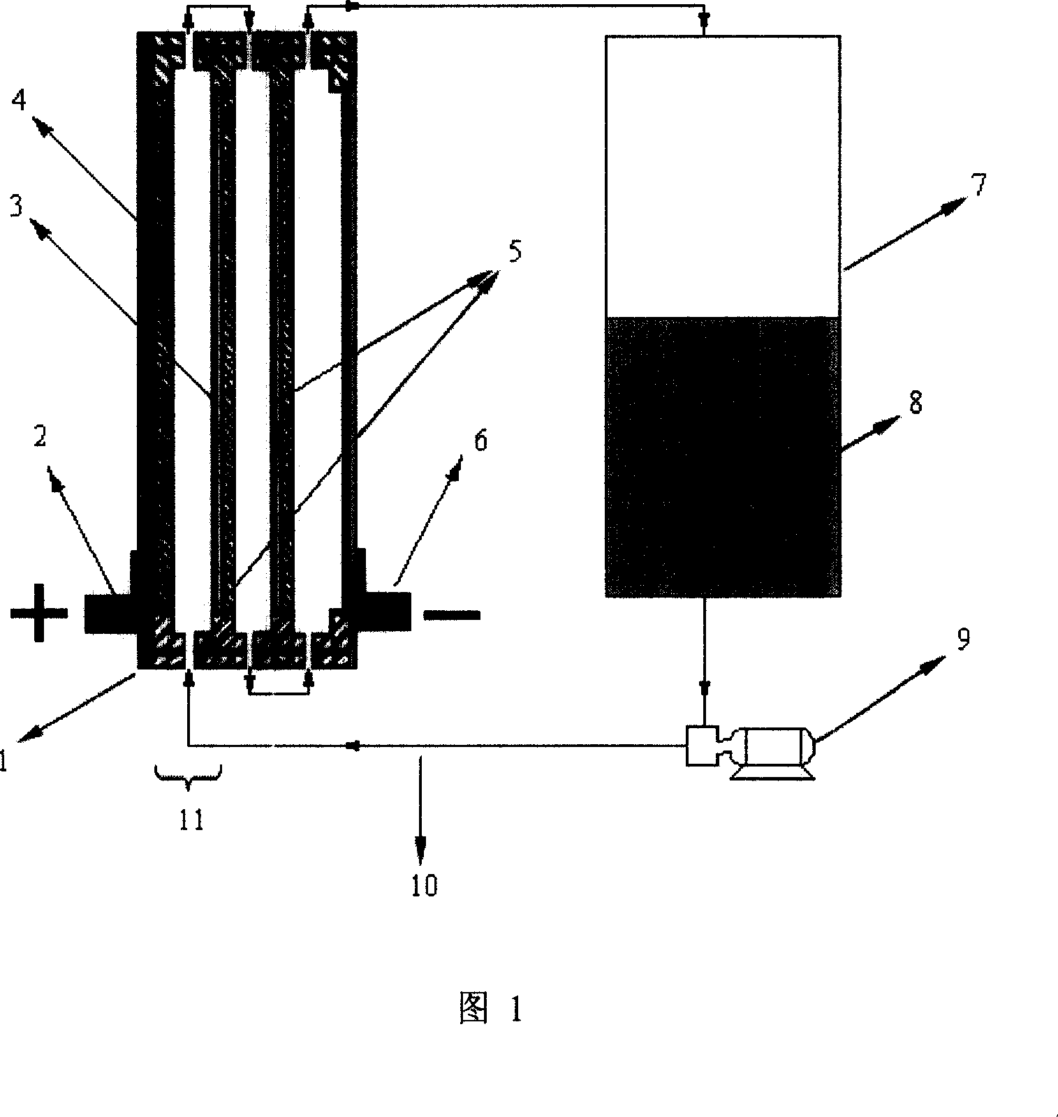
[0039] Zinc-nickel flow battery assembly

[0040] Arrange the positive and negative electrodes in a suitable container in a positive and negative manner, reserve a certain gap between the electrodes, set up an electrolyte circulation channel in the gap and seal it into a battery cell, connect the electrolyte pipeline, pump and electrolyte storage Can. While the electrolyte is flowing, charging (the negative electrode deposits zinc) and discharging (the negative electrode zinc redissolves into the electrolyte) can take place. The zinc-nickel redox flow battery prepared in this way can reach the level of all-vanadium redox flow battery in terms of specific energy and specific power, and has a higher cycle life.


PUM


Abstract

The utility model relates to a zinc-nickel sap fluid cell, which comprises a galvanic pile which is a multi-section series connection of cell monomers, electrolyte, a storage tank, a liquid pump and a plurality of pipelines; wherein, the cell monomer comprises a nickel electrode anode, a cathode current collector of deposit zinc, and electrolyte; wherein, the electrolyte is a zincous alkaline solution, and two cell monomers are connected in series via a bipolar plate. In the process of charge and discharge, the electrolyte continuously flows between the storage tank and the galvanic pile via the pipelines driven by the liquid pump. Zinc settles onto the cathode current collector and becomes a cathode active substance from the electrolyte at the time of charging, while zinc dissolves into the electrolyte from the cathode current collector at the time of discharging. The utility model has the advantages of simple fabrication technology, low cost, high cycle life and other advantages.

Description

technical field [0001] The invention relates to the combination principle and preparation method of a novel battery, in particular to the principle and preparation of a zinc-nickel flow battery, which belongs to the field of chemical industry and can be widely used in the fields of electronics industry, transportation, electric power, mining and metallurgy. Background technique [0002] The existing alkaline zinc-nickel secondary batteries have high specific energy (55-85Wh / kg), high specific power (up to 200W / kg), high open-circuit voltage (1.75V), and wide operating temperature range (-20-60 ℃), can be charged with a large current, and has abundant raw materials, low cost, and will not pollute the environment. It also has the superior performance of the extremely high capacity of the zinc negative electrode in the zinc-silver electrode and the long life of the nickel positive electrode in the nickel-cadmium battery, so it is used as a power The power supply has a wide rang...

Claims


Application Information

Patent Timeline
IPC IPC(8): H01M2/40H01M4/52H01M10/26H01M4/24H01M4/66H01M10/24H01M50/77
CPCY02E60/124Y02E60/10
Inventor 程杰张立谢自立文越华曹高萍赵鹏程杨裕生
Owner NO 63971 TROOPS PLA
Why Eureka
Try Eureka