Novel structured metallurgy cinder ladle and method of producing the same

A new type of structure and manufacturing method technology, applied in the field of metallurgy, can solve problems such as poor repairability, unfavorable cost reduction and efficiency increase, and affect performance, so as to achieve good weldability and repairability, reduce environmental pollution, and prolong service life Effect

Active Publication Date: 2009-02-18
BAOSHAN IRON & STEEL CO LTD +1
View PDF0 Cites 15 Cited by
  • Summary
  • Abstract
  • Description
  • Claims
  • Application Information

AI Technical Summary

Problems solved by technology

For example, in the process of dumping the remaining liquid steel slag or iron slag into the bunker, a large amount of dust and smoke rises, pervades the space, and the working environment is harsh; on-site pollution may lead to frequent failures of electrical equipment; harmful gases in steel slag and waste gas , Organic carbon (TOC) and heavy metals (cadmium, chromium, copper, mercury, nickel, lead, zinc) have a high emission concentration, which seriously affects the health of employees
Thus, the environmental pollution caused by the casting of slag pots is a big problem
[0005] 2. There are potential safety hazards
Because the grains of cast slag pots are larger than ordinary rolled steel (the grains are still in the original state without hot pressure processing), and the thickness is uneven (due to different cooling conditions), it is inevitable that large-scale metallurgical equipment casting such as Various defects such as shrinkage cavities, shrinkage porosity, pores, segregation, cracks, non-metallic inclusions, hot cracks, cold cracks, etc., often appear in the production site of the manufacturing and use process, causing safety hazards to production and operating personnel
[0006] 3. Based on the above reasons, various defects such as shrinkage cavity, shrinkage porosity, pores, segregation, cracks, non-metallic inclusions, hot cracks, cold cracks, etc. inevitably exist in the casting of large-scale metallurgical equipment, which seriously affect its performance
[0007] 4. Based on the above reasons, the cast slag tank has poor weldability, poor repairability, and high maintenance costs
Thus, the service life of the casting slag tank is short
[0008] Five. Also based on the casting of slag pots, there are always reasons for various defects, which make the slag pots scrapped after several months of use
On the other hand, due to the large amount of slag pots used, for example, taking a large iron and steel enterprise in China as an example, in recent years, only 5.3 cubic meters of slag pots need to consume more than 100 slag pots per year, resulting in the current use of casting slag pots The cost is extremely high, which is not conducive to cost reduction and efficiency increase

Method used


Image

  • Novel structured metallurgy cinder ladle and method of producing the same
  • Novel structured metallurgy cinder ladle and method of producing the same
  • Novel structured metallurgy cinder ladle and method of producing the same

Examples


Embodiment 1

[0064] (1) Material selection or material selection: Choose 3-8 wide and thick alloy steel plates such as carbon steel or low alloy steel such as 16Mn (Q345B, C, D), SM490 (B, C). The thickness of the steel plate ranges from 40mm to 80mm.

[0065] (2) Blanking and groove processing: "X" grooves are used for the welding of the thick plate of the tank body, the reinforcement flange of the mouth, the main plate of the overturned force-bearing part, and the longitudinal main rib plate of the trunnion force-bearing area. The groove of the bottom plate of the base adopts "K" type, and the other adopts unilateral "V" groove. Groove angle 35°~55°. Cutting by flame plus mechanical method (automatic).

[0066] (3) Steel plate pressing (rolling): Adopt normal temperature cold working pressing method.

[0067] (4) Tank (cylinder) welding: automatic submerged arc welding is adopted. Use H08Mn, H08MnA, H10Mn2 or H08Mn2Si etc. for welding wire. Manual CO2 gas shielded welding can also b...

Embodiment 2

[0091] Except following, other is the same as embodiment 1, and its volume of the present invention is made respectively the slag tank etc. of 5.3 cubic meters, 15 cubic meters, 18 cubic meters to 33 cubic meters.

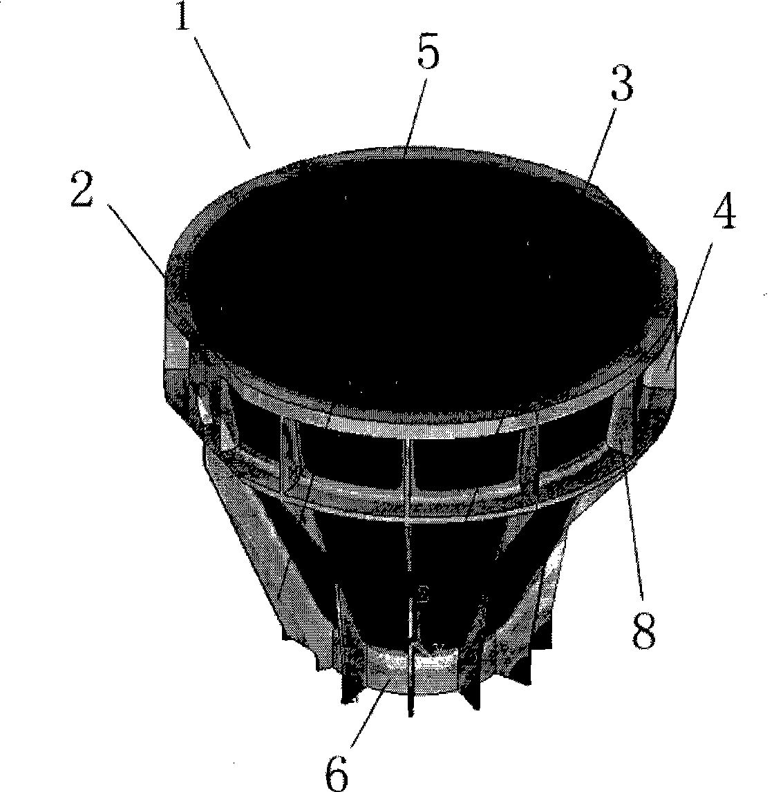
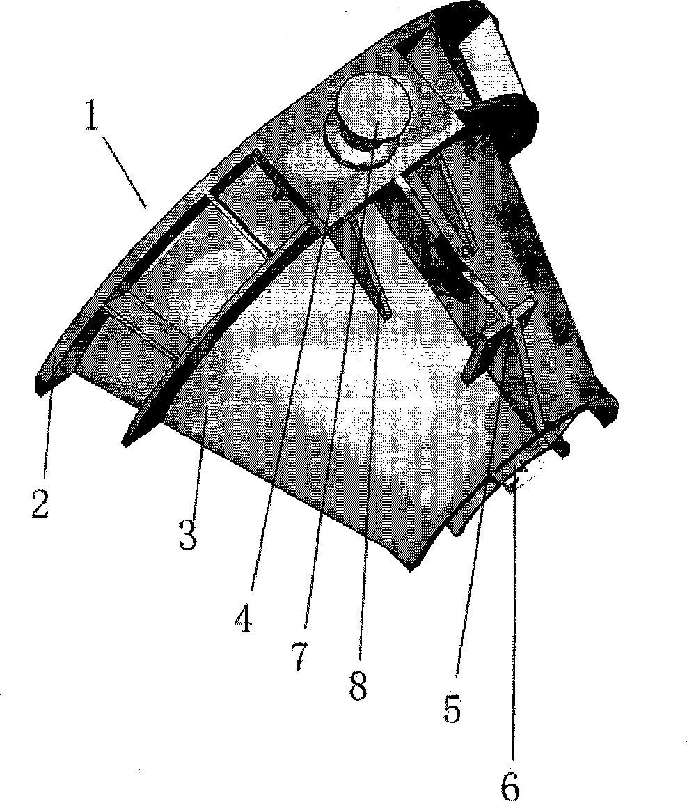
[0092] Material selection or material selection: choose 8-12 wide and thick carbon steel plates such as 20g, 20#, and 25#. It is formed by rolling or rolling forming. The steel plate thickness ranges from 80mm to 120mm; tank body welding: automatic electroslag welding; the metallurgical slag tank with the new structure adopts a tank wall inclination with a slope (α) in the range of 75°-55°. The bottom of the tank adopts a "arc bottom" structure, that is, a concave arc-shaped steel plate is used as the slag tank base and the steel plate as the tank wall is welded together, and a reinforcing rib plate is welded at the lower part of the concave arc-shaped slag tank base.

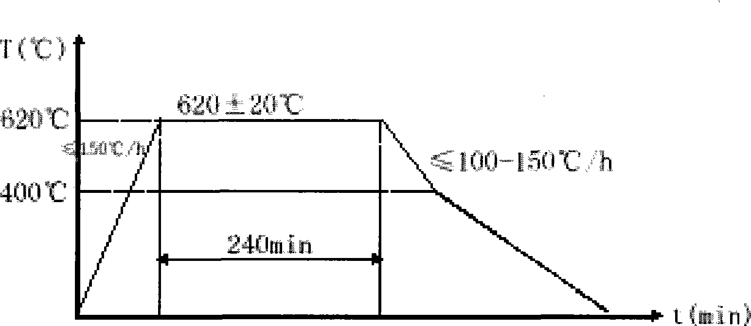
[0093]Cooling rate: 90-120°C / h; In addition to the outer peripheral edge of the tank mouth, the...


PUM

PropertyMeasurementUnit
thicknessaaaaaaaaaa
angleaaaaaaaaaa
thicknessaaaaaaaaaa

Abstract

The invention discloses a metallurgical slag tank with a novel structure which is a tank-shaped container used for holding melting steel (iron) slag with a bottom diameter larger than a mouth diameter. The invention is characterized in that the metallurgical slag tank is welded by steel plates. According to the metallurgical slag tank of a novel structure, a welding technique is used to weld the steel plates into the tank, thus reducing the environment pollution to a large extent. As the crystal grains of the steel plates forming the wall of the metallurgical slag tank are uniform in thickness and almost does not have the defects of shrinkage cavity, shrinkage porosity, air hole, segregation, crack, non metallic inclusion, thermal fragment, cold cracking, and the like; and as the crystal grains of the steel plates forming the wall of the metallurgical slag tank are like common rolling steel, the solderability and the maintainability of the slag tank are good; the service life of the slag tank can be greatly prolonged; the safety troubles often appeared in a production field like the cracking of the slag tank can be eliminated; the cost is reduced to a large extent.

Description

technical field [0001] The invention relates to the field of metallurgy, in particular, the invention relates to a metallurgical slag tank with a new structure for metallurgical casting and a manufacturing method thereof. Background technique [0002] The slag pot is a container for holding steel (iron) slag used in iron and steel smelting. So far, the existing slag pot is basically a container for holding steel (iron) slag cast by traditional casting techniques. [0003] There are problems in the method of manufacturing metallurgical slag tank by traditional casting process as follows: [0004] 1. Pollution of the environment. As we all know, casting is one of the most environmental protection problems in the field of machining, that is, one of the so-called "dirtiest" industries. The same is true for the casting of slag pots. For example, in the process of dumping the remaining liquid steel slag or iron slag into the bunker, a large amount of dust and smoke rises, perv...

Claims


Application Information

Patent Timeline
Patent Type & Authority Applications(China)
IPC IPC(8): C21B3/10B23P15/00B23K33/00
Inventor 廖礼宝彭程胡玉平王有龙金凤美周阳曲金光姚志军
Owner BAOSHAN IRON & STEEL CO LTD
Why Eureka
Try Eureka