

Compound cathode foil and solid electrolytic capacitor comprising same
A composite cathode and solid-state electrolysis technology, applied in the field of electrode foil, can solve the problems of poor mass production efficiency and long time, and achieve good compatibility and bonding, excellent high temperature oxidation resistance, high wear resistance and adhesion sexual effect
- Summary
- Abstract
- Description
- Claims
- Application Information
AI Technical Summary
Problems solved by technology
Method used
Image

Examples
Embodiment 1
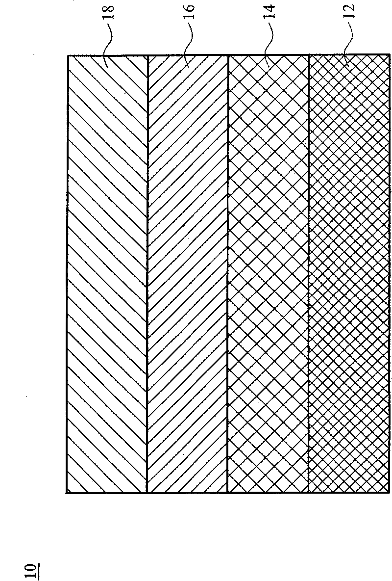
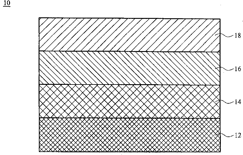
[0026] In this embodiment, the cathodic arc plasma (cathode arc plasma) coating method is used. The flat aluminum foil is used as the substrate, and titanium and graphite are used as the target materials. During the preparation process, inert gas and hydrocarbons (Hydrocarbon) are introduced. gas. Under the condition of 20 ~ 100 ℃, the pressure of the preparation process is set to 10 -4 ~2Pa, and apply a bias voltage of 0V~-500V. First, a titanium metal layer is grown on a flat aluminum substrate. Next, a titanium carbide layer is grown on the titanium metal layer. Finally, a carbon layer is grown on the titanium carbide layer to complete a composite electrode structure of aluminum / titanium / titanium carbide / carbon. The thickness of the carbon layer in the composite structure is about 288nm, and the thickness of the titanium metal layer and the titanium carbide layer is about 10-100nm.
[0027] Preparation of solid electrolytic capacitor of the present invention
[0028] T...
Embodiment 2
[0030] As in Example 1, but using zirconium instead of titanium as the metal target to complete a composite electrode structure of aluminum / zirconium / zirconium carbide / carbon, the thickness of the coating in this composite structure is about 430nm, and the zirconium metal layer and zirconium carbide The thickness of the layer is about 10 to 100 nm.
[0031] The preparation method of the solid electrolytic capacitor is the same as that in Example 1, but the aluminum / zirconium / zirconium carbide / carbon composite structure is used instead as the cathode foil. The results of its equivalent series resistance (ESR) characteristics are listed in Table 2.
Embodiment 3
[0033] As in Example 1, but using chromium instead of titanium as the metal target to complete a composite electrode structure of aluminum / chromium / chromium carbide / carbon, the thickness of the coating in this composite structure is about 430nm, and the chromium metal layer and chromium carbide The thickness of the layer is about 10 to 100 nm.
[0034] The preparation method of the solid electrolytic capacitor is the same as that of Example 1, but the composite structure of aluminum / chromium / chromium carbide / carbon is used as the cathode foil. The measured capacitance results of the solid electrolytic capacitor are listed in Table 1.
PUM
| Property | Measurement | Unit |
|---|---|---|
| Thickness | aaaaa | aaaaa |
| Thickness | aaaaa | aaaaa |
| Resistivity | aaaaa | aaaaa |
Abstract
Description
Claims
Application Information