Method for plating films of multi-arc ion plating

A multi-arc ion plating and plasma technology, which is applied in the field of physical vapor deposition (PVD), can solve the problems of reducing the friction and wear resistance and high temperature oxidation resistance of coatings, increasing the consumption of target sources, and complicated devices, etc. The effects of large particle pollution, improved cleaning quality, and increased ambient temperature

Inactive Publication Date: 2012-07-04
CHANGCHUN UNIV OF TECH
View PDF0 Cites 9 Cited by
  • Summary
  • Abstract
  • Description
  • Claims
  • Application Information

AI Technical Summary

Problems solved by technology

[0003] However, during the current multi-arc ion plating process, there are a large number of liquid particles in the plasma emitted from the arc source, which makes the surface of the coating form prominent large particle defects.
This defect not only reduces the roughness of the coating surface, but also greatly reduces the friction and wear resistance and high temperature oxidation resistance of the coating, and also limits the application of multi-arc ion plating in the preparation of nano-coatings and functional coatings.
In order to improve and eliminate the large particle defects on the surface of the multi-arc ion plating coating, researchers have proposed many improvement measures, such as improving the arc source, installing an additional magnetic field device on the cathode target to disperse the distribution of cathode spots, and reducing the emission of the cathode target in the plasma. The number and size of liquid particles, but the added device is more complicated, it is difficult to control the uniform distribution of spots, and the liquid particles in the plasma cannot be obviously eliminated, and the improvement of the surface roughness of the coating is small; another example is the plasma in the transmission process. The body is filtered, so that the large particles in the plasma are filtered out by the magnetic filter device during the transmission process, but while filtering the large particles, the deposition energy of normal ions is also reduced, the deposition efficiency is reduced, and the consumption of the target source is increased. And it can't significantly improve the large particle defects on the coating surface

Method used


Image

  • Method for plating films of multi-arc ion plating
  • Method for plating films of multi-arc ion plating
  • Method for plating films of multi-arc ion plating

Examples


Embodiment 1

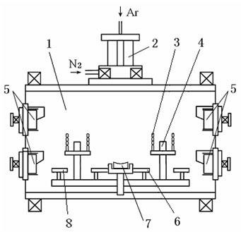
[0030] Implementation using as figure 1 The coating equipment shown has the function of multi-arc ion plating and hollow cathode ion plating. It can use the function of multi-arc ion plating or hollow cathode ion plating alone. It can also use multi-arc ion plating and ion plating at the same time. Composite ion plating function of hollow cathode ion plating; this equipment can set hollow cathode device 2 in vacuum chamber 1 while multi-arc source 5 emits plasma, and use lanthanum boride (LaB 6 ) materials to emit plasma electron beams to the anode target 7 (titanium target) and the auxiliary anode 6 and auxiliary anode 8 located in the center of the vacuum chamber 1 below; the auxiliary anode 6 surrounds the anode target 7 to make the plasma The bulk electron beam and the plasma emitted by the multi-arc source 5 perform ideal intersecting motion.

[0031] Plating (50wt%Ti, 50wt%Al)N coating is carried out in four steps.

[0032] 1) Place sample 3 in figure 1 The hollow cat...

Embodiment 2

[0040] Implementation using as figure 1In the coating equipment shown, the (70wt%Ti, 30wt%Al)N coating is plated in four steps.

[0041] 1) Place sample 3 in figure 1 The hollow cathode shown and the workpiece frame 4 in the vacuum chamber 1 of the multi-arc ion composite coating machine are vacuumed to 6.0×10 -3 Pa;

[0042] 2) Turn on the hollow cathode electron gun 2 and form a circuit with the auxiliary anode 6 and the workpiece holder 4, heat the sample 3 and the workpiece holder 4 to 350°C, and clean the surface of the sample 3 by ion sputtering;

[0043] 3) Turn on the hollow cathode electron gun 2 and form a circuit with the anode target 7 and the auxiliary anode 6 to prepare the TiN transition layer;

[0044] 4) Turn on the multi-arc source 5, turn on the hollow cathode electron gun 2 and form a circuit with the auxiliary anode 8, and prepare the (70wt%Ti, 30wt%Al)N coating.

[0045] Plating is carried out as shown in Table 2 according to the process parameters wi...

Embodiment 3

[0049] Implementation using as figure 1 The coating equipment shown is still plated (70wt%Ti, 30wt%Al) N coating in four steps, wherein the first three steps are the same as in Example 2, and the fourth step adopts a smaller hollow cathode current value and reduces the pulse Bias voltage amplitude, its process parameter table is shown in Table 3.

[0050]

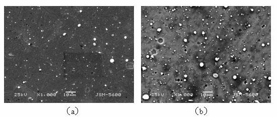
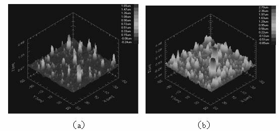
[0051] The (70wt%Ti, 30wt%Al) N coating that is plated by the above-mentioned plating method and the (70wt%Ti, 30wt%Al) N coating that is not plated by the multi-arc ion plating of the method of the present invention are subjected to surface laser Comparing the profiles, it can still be clearly seen that the (70wt%Ti, 30wt%Al)N coatings plated with the present invention have lower but equivalent number of protrusions on the surface. It shows that under this parameter of the present invention, the coating quality can still be obviously improved. Measure and compare the coating cross-sectional thickness with scanning ele...


PUM

PropertyMeasurementUnit
thicknessaaaaaaaaaa
thicknessaaaaaaaaaa
thicknessaaaaaaaaaa

Abstract

The invention relates to a method for plating films of multi-arc ion plating. The method is characterized in that a hollow cathode device is arranged in a vacuum chamber while a multi-arc source launches plasma, a hollow cathode electron gun is used for launching a high-energy plasma electron beam to an anode, and the plasma electron beam and the plasma launched by the multi-arc source carry out a mutual cross motion. The technological parameters of the plasma electron beam launched by the hollow cathode electron gun comprise 70-220 A of hollow cathode current; 10-90 percent of duty ratio; -50 to -1000 V of pulse bias voltage amplitude; 1*10-1 to 5*10-1 Pa of nitrogen partial pressure and 2*10-1 to 8*10-1 Pa of argon partial pressure. According to the method disclosed by the invention, the defect of large particles of coating surfaces can be obviously decreased while the deposition efficiency of the original multi-arc ion plating is not reduced, and therefore the quality and the using performance of coatings are increased.

Description

technical field [0001] The invention relates to a physical vapor deposition (PVD) method, in particular to a multi-arc ion plating method. Background technique [0002] Nitride coatings, carbide coatings, and carbonitride coatings are superhard coatings and functional coatings that are widely used. People have carried out various research work on preparing these coatings and improving their coating quality and performance, and developed a variety of physical vapor deposition (PVD) preparation methods, such as multi-arc ion plating (MAIP), magnetron sputtering (MS), hollow cathode ion plating (HCD), ion beam assisted deposition (IBAD), etc. Among them, the use of multi-arc ion plating has become a widely used ultra-thin coating due to its high ionization rate and ion deposition energy, the deposited coating is dense, the deposition rate is high, the bonding force with the substrate interface is good, the cost is low, and the process is simple. The main method of hard coatin...

Claims


Application Information

Patent Timeline
Patent Type & Authority Applications(China)
IPC IPC(8): C23C14/32
Inventor 吴化王淮宫文彪宋力中山弘建
Owner CHANGCHUN UNIV OF TECH
Why Eureka
Try Eureka