Method and device for hydrogen-circulating electrolysis and application of the method and device in production of aluminum oxide

An electrolysis method and a technology of hydrogen circulation, applied in the direction of electrolysis components, electrolysis process, cells, etc., can solve the problem of high energy consumption in the electrolysis of carbon fraction mother liquor, and achieve the effect of reducing energy consumption, reducing power consumption, and reducing power consumption indicators

Active Publication Date: 2012-07-25
BEIJING UNIV OF CHEM TECH
View PDF4 Cites 6 Cited by
  • Summary
  • Abstract
  • Description
  • Claims
  • Application Information

AI Technical Summary

Problems solved by technology

[0007] Aiming at the problem of high energy consumption in the electrolysis of carbon separation mother liquor in the existing alkali-soluble carbon separation method alumina production process, the present invention provides a power-saving electrolysis method based on hydrogen cycle electrolysis of carbon separation mother liquor to regenerate sodium hydroxide and sodium bicarbonate and Power-saving electrolytic cell, further significantly reducing the power consumption index of alumina production by alkali-dissolved carbon separation

Method used


Image

  • Method and device for hydrogen-circulating electrolysis and application of the method and device in production of aluminum oxide
  • Method and device for hydrogen-circulating electrolysis and application of the method and device in production of aluminum oxide
  • Method and device for hydrogen-circulating electrolysis and application of the method and device in production of aluminum oxide

Examples


Embodiment 1

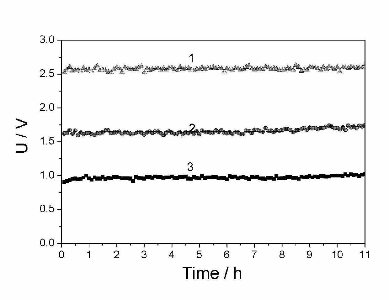
[0030] Example 1 (comparative example, using the electrolysis method of hydrogen evolution at the cathode and oxygen evolution at the anode)

[0031] The mesh nickel ruthenium electrode is used as the cathode, and the mesh titanium ruthenium electrode is used as the anode. The effective size of the electrode is 10*10cm 2 . Asahi Kasei cation exchange membrane as the diaphragm. 1.5M reagent pure Na 2 CO 3 The solution is preheated to 70°C and passed into the anode chamber of the electrolytic cell, and the 5.5M NaOH solution is preheated to 70°C and passed into the cathode chamber. After the electrolyte fills the anode chamber and the cathode chamber, temporarily stop adding the electrolyte, and slowly increase the current density from 0 to 100mA / cm within 10 minutes 2 , and then carry out constant current electrolysis. After 50min, 1.5M Na 2 CO 3 It is continuously pumped into the anode chamber of the electrolytic cell, and 5.5M NaOH is continuously pumped into the cathod...

Embodiment 2

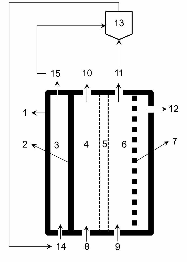
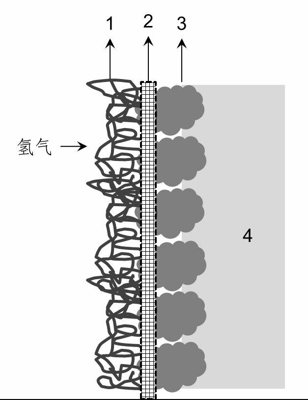
[0033] The mesh-shaped nickel-ruthenium electrode is used as the cathode, and the electrode with conductive activated carbon supported Pt-Pd as the catalyst is the hydrogen anode. The effective size of the electrode is 10*10cm 2 . Asahi Kasei cation exchange membrane as the diaphragm. 1.5M reagent pure Na 2 CO 3 The solution is preheated to 70°C and passed into the anode chamber of the electrolytic cell, and the 5.5M NaOH solution is preheated to 70°C and passed into the cathode chamber. After the electrolyte fills the anode chamber and the cathode chamber, stop adding the electrolyte temporarily, and then pass hydrogen gas with a gauge pressure of 10kPa into the hydrogen chamber, the hydrogen flow rate is about 200mL / min, and the excess unused hydrogen enters the hydrogen recovery through the upper end of the gas chamber device. The recovered hydrogen is pressurized and pumped into the cathode hydrogen chamber for use. Slowly increase the current density from 0 to 100mA / ...

Embodiment 3

[0035] The mesh-shaped nickel-ruthenium electrode is used as the cathode, and the electrode with conductive activated carbon loaded Ni-Pd as the catalyst is the hydrogen anode. The effective size of the electrode is 10*10cm 2 . Asahi Kasei cation exchange membrane as the diaphragm. After deep dealumination to remove iron and calcium containing 1.5M Na 2 CO 3 The carbon fraction mother liquor is preheated to 70°C and passed into the anode chamber of the electrolytic cell, and the 5.5M NaOH solution is passed into the cathode chamber after being preheated to 70°C. After the electrolyte is filled with the anode chamber and cathode chamber, stop adding the electrolyte temporarily, and then pass hydrogen gas with a gauge pressure of 15kPa into the hydrogen chamber, the hydrogen flow rate is about 200mL / min, and the excess unused hydrogen enters the hydrogen recovery through the upper end of the gas chamber device. The recovered hydrogen is pressurized and pumped into the cathod...


PUM


Abstract

The invention discloses a device for electrolyzing a water solution by hydrogen circulation. The device comprises a hydrogen anode, a hydrogen evolution cathode, an electrolytic cell and a hydrogen collecting and processing device, wherein the electrolytic cell is divided into an anode chamber and a cathode chamber via a diaphragm. The electrolysis method comprises the following steps: collecting the hydrogen generated by the cathode, introducing the hydrogen into an anode gas chamber, and oxidizing the hydrogen at the anode into hydrogen ions in the solution, wherein the reaction at the cathode is a hydrogen evolution reaction; and hydrogen generated by the cathode is effectively utilized at the anode, so that the hydrogen circulation is achieved, and the cell voltage is reduced to 0.9-1.3V, and the power consumption is greatly reduced. The electrolysis method and device can be applied to the production process of aluminum oxide by an alkali-dissolution and carbonization-precipitation method, i.e., sodium carbonate solution is electrolyzed based on a hydrogen-circulating electrolysis technology to obtain a sodium hydroxide solution at the cathode zone and a sodium bicarbonate solution at the anode zone, and the sodium hydroxide solution and the sodium bicarbonate solution are used for dissolving ore and breaking down a sodium aluminate solution, respectively. By using the hydrogen-circulating electrolysis for breaking down the sodium carbonate solution, the power consumption of the aluminum oxide production by the alkali-dissolution and carbonization-precipitation method can be significantly reduced.

Description

technical field [0001] The invention belongs to the technical field of electrolysis energy saving and the technical field of alumina production. Background technique [0002] Alumina is the basic raw material for the production of aluminum metal. At present, the production process that occupies a dominant position in the alumina industry is the Bayer process. The production efficiency of Bayer process alumina is restricted by the phase balance of the seed separation process, less than half of the alumina in the sodium aluminate dissolution solution can be separated by seed analysis, resulting in low production efficiency of the dissolution equipment. Niu Yinjian of Beijing University of Chemical Technology and others proposed "A process for producing alumina by alkali-dissolved carbon separation method ZL200710178670.2", proposing to use sodium hydroxide solution to leaching ore to obtain sodium aluminate solution, and use sodium bicarbonate to decompose sodium aluminate T...

Claims


Application Information

Patent Timeline
Patent Type & Authority Applications(China)
IPC IPC(8): C25B1/00C25B1/14C25B1/16C25B1/02C25B9/00C25B15/02
Inventor 万平玉唐阳钮因健陈咏梅孙艳芝
Owner BEIJING UNIV OF CHEM TECH
Why Eureka
Try Eureka